AIDA/SEYI Punching Machine/YIN SHEN MACHIY Kikuchi Machinery Manufacturing Co., Ltd. - Production Capacity/Operating Time/Tri color Light Information Data Acquisition Networked Electronic Dashboard Report Display
As a professional provider of IoT data acquisition solutions and an expert in industrial IoT data acquisition, the editor of Shanghai Data Acquisition IOT Technology Co., Ltd, (daq-iot) hereby presents the following introduction, and sincerely welcomes discussions and exchanges. Supported Communication Interfaces: CAN, RS485, Mbus, 4–20mA, Profibus, CC-Link, HART, digital I/O, etc. Industrial Protocols: Modbus RTU/TCP, HJ212, IEC104, DLT645, DLMS, IEC61850, MQTT, etc. Mail:export@daq-iot.com
Plan to proceed PLC Data AcquisitionThe current information of the project is as follows:
1) Equipment brand and quantity: 13 AIDA machines from Japan, punching machines; 4 SEYI punch presses; YIN SHEN Machinery 1 unit; 3 punch presses from Kikuchi Machinery Manufacturing Co., Ltd. in Japan
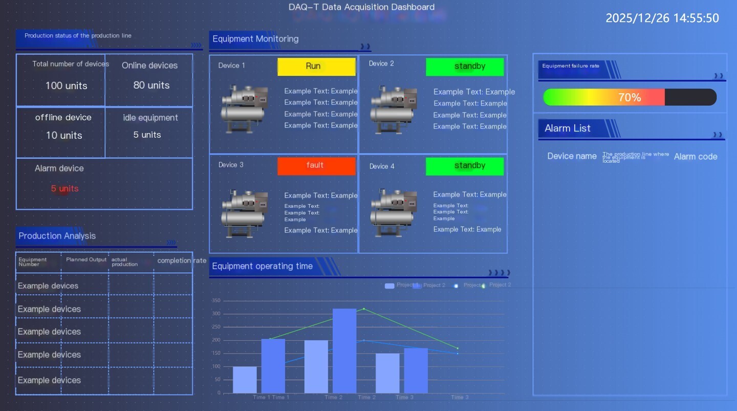
2) Note: The remaining device information is still being organized. There are a total of 70 devices.
3) Data collection content: production quantity, equipment operation timethree-color light
4) Data Usage: Electronic Kanban+Reports
5) Does the system already exist? Currently not available. We hope to provide an overall solution from collection to display
6) Implementation scope: pilot one factory first, and then carry out in two factories later
Please provide technical solutions and preliminary quotation ranges based on the above information.
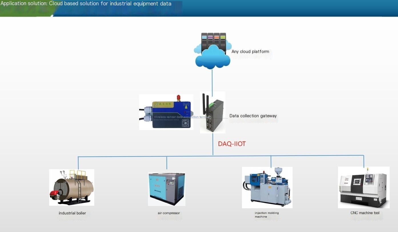
1) Overall architecture
Adopting a four layer architecture of "perception layer transport layer storage layer application layer":
1. Perception layer: By collecting stamping actions and three color lamp voltage signals through Sensor, physical signals are converted into electrical signals;
2. Transport layer: throughEdge ComputingGatewayPreprocess the collected digital signals (denoising, filtering, counting) and transmit them to the storage layer;
3. Storage layer: Using local servers or cloud servers to store data, ensuring data security and traceability;
4. Application layer: Display output, utilization rate, equipment status and other data through a visual management platform, supporting functions such as data query, report generation, and abnormal alarm.
(2) Sub indicator collection plan
1. Production Data Acquisition
Collection principle: When the punch press completes each stamping, the slider or crankshaft will complete a reciprocating motion. By installing Sensor near the moving parts, capturing and counting each motion signal, production statistics can be achieved.
1. Sensor Selection: SelectInductive proximity switch(Recommended model: DAQ-GP-IR4G), compatible with metal moving parts, detection distance 0-10mm, response frequency ≥ 1kHz, can accurately capture high-speed stamping actions; If the moving parts are non-metallic (rare), they can be selectedphotoelectric switch。
2. Installation position: On the side of the punch slide or near the crankshaft connecting rod, ensure that the proximity switch can trigger a signal after each downward punch of the slide; During installation, it is necessary to avoid the lubrication oil circuit and interference area of the equipment, and use brackets to fix it to ensure stability.
3. Signal processing: The signal output by Sensor is a switch value (DC24V), which is connected to the digital input interface of Edge Computing Gateway. Gateway has a built-in counting algorithm to denoise the signal (filter out false triggers caused by vibration), and each trigger counts as one product; If it is necessary to distinguish between qualified/unqualified products, a photoelectric switch can be installed at the discharge port or manually scanned and entered (additional scanning guns and workstation terminals need to be configured).
2. Collection of operating time
Collection principle: The operating time is based on the duration statistics of the device's operating status (running, standby, shutdown), and the device status can be determined through the linkage of the three color light status and the stamping action signal.
1. Signal acquisition: Use a voltage acquisition module (recommended model: DAQ-GP OPC ua) to collect the power supply voltage signals (AC220V or DC24V) of the red, yellow, and green indicator lights of the three color lights, and determine whether the corresponding colors are lit; At the same time, combined with the stamping action signal, distinguish the "false operation" (light on but no stamping action) state.
2. State determination logic:
-Running status (green light on+stamping action signal): Start timing until the status changes;
-Standby state (yellow light on+no stamping action signal): starts timing, commonly seen in the ready state before mold replacement preparation and material waiting;
-Shutdown status (red light on+no stamping action signal): Start timing, corresponding to fault shutdown; If none of the three color lights are on and there is no stamping action, it is also judged as a shutdown state (excluding equipment power failure, which can be assisted by power supply voltage collection).
3. Time statistics: Edge Computing Gateway has a built-in Real-time clock (RTC), which accurately records the start and end times of each state and automatically calculates the duration of each state; The planned production time is preset by the system (such as 8 hours/shift), and the utilization rate is automatically calculated.
3. Three color light information collection
1. Collection method: Directly collect the control circuit voltage signal of the three color lamp without changing the original lamp group circuit; If the three color lamp is an integrated module, voltage acquisition terminals can be connected in parallel at the power supply end of the lamp group.
2. Module selection: Select a digital input module with isolation function (such as an analog acquisition module for data acquisition IoT), support AC/DC universal voltage input, and avoid the impact of voltage fluctuations on acquisition accuracy; The module output signal is RS485(Modbus RTUProtocol), can be directly connected to the edge Gateway.
3. Status transmission: GatewayReal-timecollects the three color light status signals output by the module, converts them into text identifiers of "green running", "yellow standby", and "red fault", and synchronously transmits them to the application layer to achieve the display of statusReal-time.
评论
发表评论