Air compressor monitoring software Hardware integrated solution
As a professional provider of IoT data acquisition solutions and an expert in industrial IoT data acquisition, the editor of Shanghai Data Acquisition IOT Technology Co., Ltd, (daq-iot) hereby presents the following introduction, and sincerely welcomes discussions and exchanges. Supported Communication Interfaces: CAN, RS485, Mbus, 4–20mA, Profibus, CC-Link, HART, digital I/O, etc. Industrial Protocols: Modbus RTU/TCP, HJ212, IEC104, DLT645, DLMS, IEC61850, MQTT, etc. Mail:export@daq-iot.com
1、 Overview of the Plan
This solution addresses the pain points of air compressor equipment in industrial scenarios, providing a software integrated solution that combinesHardwarewithsolutionconversion, centralized monitoring, intelligent control, and energy efficiency analysis. The plan adopts the conversion fromProtocoltoGateway+Wireless Communication Management Machine/Layered architecture of intelligent terminal+self-developed Zhihu platform+configuration visualization software: converting Protocol from Protocol to Gateway to achieve private Protocol of all brand air compressors to standardModbusRTUThe conversion of data is completed by a wireless communication management machine/intelligent terminal, which wirelessly reports data and connects with the cloud platform. Combined with a self-developed monitoring platform, it helps enterprises achieve digital and intelligent management of air compressor equipment, reduce costs, improve equipment operating efficiency, and achieve energy conservation and consumption reduction.
The plan has the following core values:
●Full brand access:Covering mainstream air compressors, centrifuges, and supporting equipment at home and abroad, theProtocollibrary has over 190 types of controller models built-in, which are plug and play.
●Protocol Conversion:Convert fromProtocoltoGateway, and unify the privateProtocolof each brand into a standard Modbus RTU. The upper computer/PLC/DCS can be connected with one click.
●Wireless reporting:By supporting wireless communication management machines/intelligent terminals, Modbus RTU data can be reported to any public cloud platform via 4G/Ethernet, supportingMQTT/TCP/UDP/HTTP and various other Protocol.
●Centralized monitoring:Real-time collects operational status and process parameters, displays them on a large configuration screen for visualization, and bids farewell to manual inspection and meter reading.
●Intelligent Joint Control:Automatic rotation, on-demand start stop, fault isolation, achieving group control and energy-saving operation of air compressors.
●Data driven:Historical data storage and energy efficiency analysis support preventive maintenance and operational optimization decisions.
2、 Supported air compressor brands and model types
This solution supports mainstream global air compressor brands, covering various types of air compressors such as screw, centrifugal, and vortex compressors, as well as supporting equipment such as dryers, filters, and waste heat recovery machines. As of now, theProtocollibrary has been adapted to over 190 controller models, with core supported brands including:
2.1 Core Support Brands
●International mainstream brands:Ingersoll Rand, Atlas Copco, Sullair, Hitachi, Kobelco, Boge, CompAir, Gardner Denver, Orion, etc.
●Domestic brands:Prudential, Fusheng, Yunaites, SaZhen, Baos, LinggeFeng, DeMan, BaoDe, Jaguar, AiGao, Qiangshi, JiaDe, Elide, etc.
●General supporting equipment:General supporting equipment such as refrigerated dryers, waste heat recovery machines, filters, dryers, vacuum pumps, blowers, and dry contact air compressors.
●Communication Protocol supports:Protocol conversionGatewaymainstream support RS-485ModbusRTU Protocol output (some Atlas models are compatible with CAN bus), and a singleGatewaycan be connected to at most 10 air compressor equipment at the same time; The data reporting to the cloud platform is undertaken by the supporting wireless communication management machine/intelligent terminal, which supports communication methods such as Ethernet and MQTT.
2.2 Adaptation Model Statistics
The following table shows the distribution of controller models and brands that have been adapted to theProtocollibrary in this scheme (a total of 156 air compressors and 37 centrifuges):
| brand | Number of compatible models for air compressors | Number of centrifuge compatible models | total |
| Ingersoll Rand | 56 | 16 | 72 |
| Erlide | 15 | — | 15 |
| Sullair | 10 | 3 | 13 |
| Kobelco | 12 | — | 12 |
| Hitachi | 9 | — | 9 |
| Plext | 8 | — | 8 |
| Atlas | 3 | 5 | 8 |
| Fusheng | 6 | 1 | 7 |
| Yunaites | 5 | — | 5 |
| Berg | 3 | — | 3 |
| Dengfu | 2 | 1 | 3 |
| Strong Time | 2 | — | 2 |
| Bao Si | 1 | 1 | 2 |
| DeMan air compressor | 2 | — | 2 |
| Zhongfu Shenying Filter | 2 | — | 2 |
| Compair | 2 | — | 2 |
| pioneer | — | 2 | 2 |
| Alfred | — | 2 | 2 |
| Hanwha | — | 2 | 2 |
| ENC frequency converter | 1 | — | 1 |
| Yuan Yi refrigerated dryer | 1 | — | 1 |
| Inovance | 1 | — | 1 |
| Sa Zhen | 1 | — | 1 |
| Omron | 1 | — | 1 |
| Jierong heat recovery machine | 1 | — | 1 |
| Huanneng Phoenix Waste Heat Recovery Machine | 1 | — | 1 |
| Ailide medium press machine | 1 | — | 1 |
| Universal dry contact air compressor 1 | 1 | — | 1 |
| Universal dry contact air compressor 2 | 1 | — | 1 |
| linguaphone | 1 | — | 1 |
| Haituobin | 1 | — | 1 |
| Aigle | 1 | — | 1 |
| Orion | 1 | — | 1 |
| Carter | 1 | — | 1 |
| Jaguar | 1 | — | 1 |
| Jiade | 1 | — | 1 |
| Baldor | 1 | — | 1 |
| heroic | — | 1 | 1 |
| Wancong Thermal Heat Recovery Machine | — | 1 | 1 |
| Lingyu | — | 1 | 1 |
| Magnetic Valley | — | 1 | 1 |
| total | 156 | 37 | 193 |
Note: Please refer to Section 2.3 for the complete list of controller communication models; The new model is continuously adapting, and non-standard Protocol supports customized development.
2.3 List of Controller Communication Models
The following is a complete list of communication models of air compressors and centrifuge controllers that have been adapted to this scheme Gateway. When connected on site, the corresponding Gateway model can be selected according to the brand and controller model to achieve debugging free docking.
(1) Communication list of air compressor controller
| serial number | brand | Air compressor series | Controller Model | Communication bus |
| 1 | Ingersoll Rand | VSD | KT | RS-485 |
| 2 | Ingersoll Rand | V | KT | RS-485 |
| 3 | Ingersoll Rand | SG | RS-485 | |
| 4 | Ingersoll Rand | M、R | XE70M | RS-485 |
| 5 | Ingersoll Rand | M、R | XE90M | RS-485 |
| 6 | Ingersoll Rand | V | fierce tiger | RS-485 |
| 7 | Ingersoll Rand | KOS400 | RS-485 | |
| 8 | Ingersoll Rand | SE | IRLAN to 485 | RS-485 |
| 9 | Ingersoll Rand | VSD | KT frequency conversion new model 1 | RS-485 |
| 10 | Ingersoll Rand | VSD | XE90M/XE145M | RS-485 |
| 11 | Ingersoll Rand | VSD | SGVSD | RS-485 |
| 12 | Ingersoll Rand | M、R | XE145M | RS-485 |
| 13 | Ingersoll Rand | SMxxVSD | KT frequency conversion new model 2 | RS-485 |
| 14 | Ingersoll Rand | SMxxV | KT power frequency new model 1 | RS-485 |
| 15 | Ingersoll Rand | M、RVSD | XE90MVSD | RS-485 |
| 16 | Ingersoll Rand | SG | RS-485 | |
| 17 | Ingersoll Rand | XE145M Model 2 | RS-485 | |
| 18 | Ingersoll Rand | KOS500 | RS-485 | |
| 19 | Ingersoll Rand | VSD | VSD-XE145M | RS-485 |
| 20 | Ingersoll Rand | VSD | XE145M | RS-485 |
| 21 | Plext | MAM_KY | RS-485 | |
| 22 | Plext | MAM_200 | RS-485 | |
| 23 | Plext | MAM_6090 | RS-485 | |
| 24 | Plext | MAM_KY12S | RS-485 | |
| 25 | Plext | Variable frequency type | MAM_VSD_1 | RS-485 |
| 26 | Plext | MAM_YL | RS-485 | |
| 27 | Plext | MAM6080/6090_2 | RS-485 | |
| 28 | Plext | MAM8070 | RS-485 |
| 29 | Atlas | MK4、MK5 | Shenzhen module | CAN/RS-485 |
| 30 | Atlas | MK4 | MK4 | CAN |
| 31 | Atlas | MK5 | MK5 | CAN |
| 32 | Sullair | Standard Type 1 | RS-485 | |
| 33 | Sullair | Type 4 | RS-485 | |
| 34 | Sullair | oil-free machine | RS-485 | |
| 35 | Sullair | Luxury Type 2 | RS-485 | |
| 36 | Sullair | EC2000 | RS-485 | |
| 37 | Sullair | SDS | RS-485 | |
| 38 | Sullair | STS | RS-485 | |
| 39 | Sullair | DS series | RS-485 | |
| 40 | Sullair | vacuum pump | Luxury Type 4 | RS-485 |
| 41 | Sullair | oil-free machine | Luxury Type 6 | RS-485 |
| 42 | Hitachi | N2 micro oil | HC_1 | RS-485 |
| 43 | Hitachi | N2 oil-free | HC_2 | RS-485 |
| 44 | Hitachi | N1 oil-free (using transfer PLC) | HC_3 | RS-485 |
| 45 | Hitachi | 4G | HC_4 | RS-485 |
| 46 | Hitachi | TH series power frequency | EPC-2000 | RS-485 |
| 47 | Hitachi | TH series frequency converter | EPC-2000 | RS-485 |
| 48 | Hitachi | Micro oil single-stage compression | HC-5 | RS-485 |
| 49 | Hitachi | Micro oil single-stage compression | HC-CP650 | RS-485 |
| 50 | Hitachi | Micro oil single-stage compression - Envision | HC-INVT | RS-485 |
| 51 | Berg | V120 | RS-485 | |
| 52 | Berg | BOGE_DC_1 | RS-485 | |
| 53 | Berg | BOGE_1 | RS-485 | |
| 54 | Kobelco | ALE/FE | KB_1 | RS-485 |
| 55 | Kobelco | Kobelion | KB_2 | RS-485 |
| 56 | Kobelco | AG75 | KB_3 | RS-485 |
| 57 | Kobelco | AG75 | KB_4 | RS-485 |
| 58 | Kobelco | KB_5 | RS-485 | |
| 59 | Kobelco | ALE_2 | KB_6 | RS-485 |
| 60 | Kobelco | KB_7 | RS-485 | |
| 61 | Kobelco | KB_8 | RS-485 | |
| 62 | Kobelco | KB_9 | RS-485 | |
| 63 | Kobelco | KB_10 | RS-485 | |
| 64 | Strong Time | QS_1 | RS-485 | |
| 65 | Strong Time | E75 | Hailipu inverter direct control | RS-485 |
| 66 | ENC frequency converter | EN600 | RS-485 | |
| 67 | Yuan Yi refrigerated dryer | YY_RD_1 | RS-485 | |
| 68 | Fusheng | SA | FS_SA | RS-485 |
| 69 | Fusheng | FS_MAM | RS-485 | |
| 70 | Fusheng | FS_1200 | RS-485 | |
| 71 | Fusheng | FS_MAM_2 | RS-485 | |
| 72 | Fusheng | SA | FS_SA250 | RS-485 |
| 73 | Fusheng | FS_MAM_3 | RS-485 | |
| 74 | Ingersoll Rand | XE145M | RS-485 | |
| 75 | Ingersoll Rand | SE | RS-485 | |
| 76 | Ingersoll Rand | XE145M_5 | RS-485 | |
| 77 | Ingersoll Rand | XE145M_6 | RS-485 | |
| 78 | Ingersoll Rand | XE145M_7 | RS-485 | |
| 79 | Ingersoll Rand | SG_3 | RS-485 | |
| 80 | Ingersoll Rand | S3 | RS-485 | |
| 81 | Ingersoll Rand | XE145M_VSD_2 | RS-485 | |
| 82 | Ingersoll Rand | XE145M_8 | RS-485 | |
| 83 | Ingersoll Rand | S1 | RS-485 | |
| 84 | Inovance | frequency converter | cp700 | RS-485 |
| 85 | Yunaites | EPC-2000 | RS-485 | |
| 86 | Yunaites | EPC-2000_2 | RS-485 | |
| 87 | Yunaites | EPC-2000 frequency converter | RS-485 | |
| 88 | Yunaites | EPC-2000_3 | RS-485 | |
| 89 | Yunaites | container | EPC-2000PX | RS-485 |
| 90 | Sa Zhen | VK070 | RS-485 | |
| 91 | Bao Si | ZMF02 | RS-485 | |
| 92 | Ingersoll Rand | KT_VSD | RS-485 | |
| 93 | Ingersoll Rand | XE70M_2 | RS-485 | |
| 94 | Ingersoll Rand | CMC_V3_SH300W | RS-485 | |
| 95 | Ingersoll Rand | E200ie oil-free machine | XE145M_9 | RS-485 |
| 96 | Ingersoll Rand | XE90M_VSD_4 | RS-485 | |
| 97 | Erlide | dual motor | AIR_TSFC | RS-485 |
| 98 | Erlide | Terry oxygen concentrator | AIR_OXY | RS-485 |
| 99 | Erlide | Power frequency machine | AIR_TSFC | RS-485 |
| 100 | Erlide | Single stage frequency converter | AIR_TSA | RS-485 |
| 101 | Erlide | Cold dry integrated machine | AIR_VSD | RS-485 |
| 102 | Erlide | Dual motor (new program) | AIR_TSFC_2 | RS-485 |
| 103 | Erlide | Single container | AIR_IES_1 | RS-485 |
| 104 | Erlide | Single stage frequency converter with integrated display and control | AIR_VSD_2 | RS-485 |
| 105 | Erlide | Single container (new program) | AIR_IES_2 | RS-485 |
| 106 | Omron | E5CC | RS-485 | |
| 107 | Jierong heat recovery machine | JR_1 | RS-485 | |
| 108 | DeMan air compressor | MD8500 | RS-485 | |
| 109 | Huanneng Phoenix Waste Heat Recovery Machine | RS-485 | ||
| 110 | Zhongfu Shenying Filter | ZF_1 | RS-485 | |
| 111 | Zhongfu Shenying Filter | ZF_2 | RS-485 | |
| 112 | DeMan air compressor | MD8500_TCP | RS-485 | |
| 113 | Ailide medium press machine | EBV_8_40 | Huichuan H2u | RS-485 |
| 114 | Universal dry contact air compressor 1 | |||
| 115 | Universal dry contact air compressor 2 | |||
| 116 | Ingersoll Rand | XE145M_VSD_3 | RS-485 | |
| 117 | Ingersoll Rand | LM_1 | RS-485 | |
| 118 | Ingersoll Rand | LM_VSD_1 | RS-485 | |
| 119 | Ingersoll Rand | KT_VSD_2 | RS-485 | |
| 120 | Ingersoll Rand | XE145M_VSD_4 | RS-485 | |
| 121 | Ingersoll Rand | LM_VSD_2 | RS-485 | |
| 122 | Ingersoll Rand | LM_2 | RS-485 | |
| 123 | Ingersoll Rand | XE90M_VSD_3 | RS-485 | |
| 124 | Ingersoll Rand | V100T | RS-485 | |
| 125 | Ingersoll Rand | LM_VSD_3 | RS-485 | |
| 126 | Ingersoll Rand | LM_3 | RS-485 | |
| 127 | Ingersoll Rand | LM_VSD_4 | RS-485 | |
| 128 | Ingersoll Rand | LM_VSD_5 | RS-485 | |
| 129 | Ingersoll Rand | LM_VSD_6 | RS-485 | |
| 130 | Ingersoll Rand | KT_VSD_3 | RS-485 | |
| 131 | Ingersoll Rand | SG_4 | RS-485 | |
| 132 | Ingersoll Rand | XE145M_10 | RS-485 | |
| 133 | Ingersoll Rand | LM_VSD_7 | RS-485 | |
| 134 | Ingersoll Rand | LM_4 | RS-485 | |
| 135 | linguaphone | HD37 | RS-485 | |
| 136 | Compair | DelcosTs power frequency | RS-485 | |
| 137 | Compair | DelcosTs frequency converter | RS-485 | |
| 138 | Haituobin | blower | RS-485 | |
| 139 | Aigle | BPM110 | Huichuan PLC | RS-485 |
| 140 | Orion | Omron CVs | RS-485 | |
| 141 | Dengfu | SAV250 | RS-485 | |
| 142 | Dengfu | DH55VSD | RS-485 | |
| 143 | Erlide | Single container with heat recovery | AIR_IES_3 | RS-485 |
| 144 | Erlide | Container dual main controller | AIR_IES2_M | RS-485 |
| 145 | Erlide | Container Double Unit 1 # | AIR_IES2_1 | RS-485 |
| 146 | Erlide | Container Double Unit 2 # | AIR_IES2_2 | RS-485 |
| 147 | Erlide | Container unit (Nvidian GD300) | AIR_IES_4 | RS-485 |
| 148 | Erlide | Container unit (Nvidian GD350) | AIR_IES_5 | RS-485 |
| 149 | Carter | KT_VSD_1 | RS-485 | |
| 150 | Jaguar | JB_1 | RS-485 | |
| 151 | Jiade | container | JD_1 | RS-485 |
| 152 | Kobelco | AG75 | KB_11 | RS-485 |
| 153 | Kobelco | VS160+AR | KB_12 | RS-485 |
| 154 | Baldor | BD-30GS | BD_30GS | RS-485 |
| 155 | Ingersoll Rand | SVT vacuum pump | RS-485 | |
| 156 | Ingersoll Rand | VS680 vacuum pump | RS-485 |
(2) Communication list of centrifuge controller
| serial number | brand | Air compressor series | Controller Model | Communication bus |
| 1 | pioneer | RS-485 | ||
| 2 | Ingersoll Rand | C700,C1000 | Xe145m | RS-485 |
| 3 | Ingersoll Rand | C700,C1000 | Xe145DCU | RS-485 |
| 4 | Sullair | SL400 | RS-485 | |
| 5 | Atlas | MK4 | RS-485 | |
| 6 | Atlas | MK5 | RS-485 | |
| 7 | Atlas | MK5 | RS-485 | |
| 8 | Ingersoll Rand | CMCBCM2.x | RS-485 | |
| 9 | Fusheng | EDC-PLC | RS-485 | |
| 10 | pioneer | S7-1215 | RS-485 | |
| 11 | Atlas | MK5 | CAN | |
| 12 | Atlas | ZH630 | MK5 | CAN |
| 13 | Alfred | EDC | RS-485 | |
| 14 | Alfred | R150 | RS-485 | |
| 15 | Hanwha | SM4100 | RS-485 | |
| 16 | Hanwha | SM4000 | RS-485 | |
| 17 | Ingersoll Rand | C700 | Xe145DCU | RS-485 |
| 18 | Ingersoll Rand | NX8000 | RS-485 | |
| 19 | Ingersoll Rand | NX8000_2 | RS-485 | |
| 20 | Ingersoll Rand | TA6000 | RS-485 | |
| 21 | Ingersoll Rand | TA6000_2 | RS-485 | |
| 22 | Ingersoll Rand | TA6000_3 | RS-485 | |
| 23 | Ingersoll Rand | NX5000 | RS-485 | |
| 24 | Ingersoll Rand | TA6000_4 | RS-485 | |
| 25 | Ingersoll Rand | TA6000_5 | RS-485 | |
| 26 | Ingersoll Rand | C700_2 | Xe145DCU | RS-485 |
| 27 | Sullair | SL400 | RS-485 | |
| 28 | Sullair | TRE | RS-485 | |
| 29 | Bao Si | VT | RS-485 | |
| 30 | Dengfu | VB1200 | RS-485 | |
| 31 | heroic | HM850 | RS-485 | |
| 32 | Wancong Thermal Heat Recovery Machine | CTY600 | RS-485 | |
| 33 | Lingyu | LY_DB600 | RS-485 | |
| 34 | Magnetic Valley | CG400 | CG/A400 | RS-485 |
| 35 | Ingersoll Rand | TA6000_6 | RS-485 | |
| 36 | Ingersoll Rand | NX8000_3 | RS-485 | |
| 37 | Ingersoll Rand | TA3000 | RS-485 |
3、 Hardware Scheme Design
3.1 Hardware Architecture Overview
The scheme Hardware adopts a clear hierarchical architecture, with clear responsibilities and each layer performing its own duties, ensuring the decoupling of Protocol conversion and data reporting functions, facilitating on-site deployment and maintenance:
| Hardware hierarchy | core equipment | Main Responsibilities | communication interface |
| Protocol Conversion Layer | Air compressor Protocol conversion acquisition Gateway(DAQ-GP-AMmodbus) | Connect to the privateProtocolair compressor controller and convert it to standard Modbus RTU output | Downward: MKLAN connected to air compressor; Upstream: RS485 Modbus RTU |
| Data reporting layer | Wireless communication management machine/wireless intelligent terminal | Collect Modbus RTU data output fromGatewayand report it to the cloud platform via 4G/Ethernet | Downstream: RS485 acquisition; Upstream: 4G/Ethernet (MQTT/TCP/HTTP, etc.) |
| Application Display Layer | Industrial computer/cloud monitoring platform | Data storage, configuration visualization, intelligent control, alarm and reporting | Local or cloud deployment, browser access |
Explanation: The air compressor Protocol conversion Gateway is only responsible for converting the private Protocol of the air compressor into standard Modbus RTU output, and does not directly have wireless reporting and cloud platform integration capabilities; If data needs to be reported to the public cloud platform orRemote Monitoringcenter, a supporting wireless communication management machine or wireless intelligent terminal needs to be added on the upstream side ofGatewayto complete the collection, encapsulation, and wireless reporting of Modbus RTU data.
3.2 Conversion and acquisition of air compressor Protocol Gateway (DAQ-GP AMmodbus)
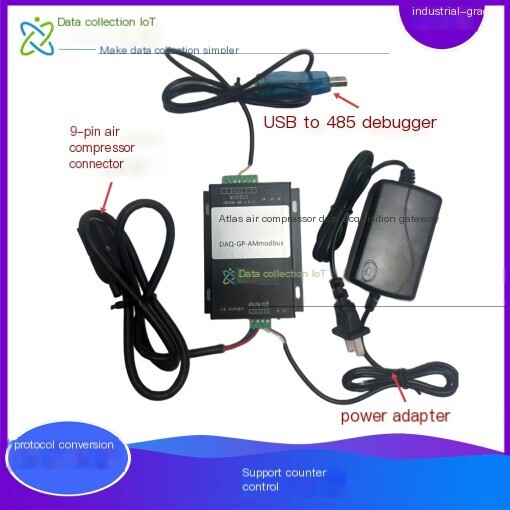
The DAQ-GP AMmodbus series air compressor Protocol conversion Gateway is a Gateway device launched by Shanghai DAQ-IoT Network Technology Co., Ltd. for the conversion and reverse control of [TERM0042TTOKEN] and Protocol for air compressors. It can be used for mainstream air compressor equipment [TERM0033TTOKEN] to quickly connect air compressor data to third-party systems such as PLC or DCS.
Through this Gateway, the operating status and parameters of the air compressor can be monitored, and the start, stop, loading, and unloading of the air compressor can also be controlled through serial communication. ThisGatewaycan connect 5 Atlas/Ingersoll Rand and other air compressors (up to 10) at the same time without additional configuration to form an air compressor group control network. The upper computer software or PLC can be connected to the networkReal-timeusing Modbus RTU via RS485 interface.
3.2.1 Core parameter specifications
| project | Parameter Specifications |
| model | DAQ-GP AMmodbus (customizable brand specific models) |
| core functionality | Air compressor Data Acquisition, private Protocol converted to standard Modbus RTU, remote start stop/load unload reverse control, multi device cluster access |
| interface configuration | MKLAN air compressor dedicated interface (DB9), A/B-RS485 Modbus interface |
| working power supply | 220VAC,60mA |
| Dimensions | 122×84×24(mm) |
| working environment | Temperature -30 ℃~75 ℃, humidity 0~95% |
| Output Protocol | RS485 Modbus RTU (standard) for upper computer/PLC/wireless terminal to read |
| Supporting attachments | Power adapter, air compressor communication connector |
3.2.2 Gateway Selection Instructions
| model | Feature Description |
| DAQ-GP-AMmodbus-Atlas | Connect Atlas Copco MK2, MK4 and MK5 computer controllers |
| DAQ-GP-AMmodbus-Ingersoll | Connect Ingersoll air compressor |
| DAQ-GP-AMmodbus-XX | Other brands of air compressors, such as Sullair, Fusheng, Kaishan, Shengang, etc |
| …… | Customization (developed specifically for the non-standard controllerProtocolmodelGateway) |
3.2.3 Product Features
●Electrical characteristics:Working power supply 220VAC, 60mA, suitable for industrial site power supply environment.
●Communication characteristics:Standard RS485 Modbus RTU output, the upper computer/PLC/wireless terminal reads data from Modbus slave addresses 1-10; The MKLAN interface is connected to the air compressor controller in a one to many manner, and the A/B terminals are Modbus (485) interfaces.
●Structural characteristics:Size specification 122 × 84 × 24 (mm), rail/wall mounted, compact structure.
●Work environment:Working temperature -30 ℃~75 ℃, humidity 0~95%, suitable for various industrial site environments.
●Ability boundary:Note: Gateway itself only outputs Modbus RTU and does not directly support wireless reporting such as 4G/MQTT; The wireless reporting and cloud platform integration capability is provided by the supporting wireless communication management machine/intelligent terminal (see section 3.3).
3.3 Wireless Communication Management Machine/Wireless Intelligent Terminal
When on-site data needs to be reported to the public cloud platform orRemote Monitoringcenter, a supporting wireless communication management machine or wireless intelligent terminal needs to be added on the upstream side of theProtocolconversion. This device serves as the core of the data reporting layer Hardware, responsible for collecting Modbus RTU data output by Gateway, and reporting it to any public network server or cloud platform via 4G/Ethernet via MQTT/TCP/UDP/HTTP, etc. Protocol.
3.3.1 Core parameter specifications
| project | Parameter Specifications |
| Device Type | Industrial grade wireless communication management machine/wireless intelligent terminal |
| core functionality | Modbus RTU Data Acquisition, Protocol encapsulation, 4G/Ethernet wireless reporting, cloud platform docking, breakpoint resume transmission |
| Downstream acquisition interface | RS485 Modbus RTU master station, capable of polling and collecting multiple Protocol conversion Gateway output data |
| Upstream communication method | 4G LTE full network/Ethernet (RJ45) |
| Support Protocol | MQTT/TCP/UDP/HTTP/SSL, Customizable for other communications Protocol |
| data forwarding | Any public network server/cloud platform |
| working power supply | 220VAC or DC wide voltage power supply |
| working environment | Industrial grade, temperature range of -30 ℃ to 75 ℃, suitable for various industrial sites |
3.3.2 Functional Characteristics
●Data Acquisition:As a Modbus RTU master station, collect air compressor data from Protocol converted to Gateway by polling from slave addresses 1 to 10, aggregate and report it uniformly.
●Wireless uplink:Supports 4G LTE full network and Ethernet uplink, suitable for various on-site environments with or without network.
●Multiple Protocol reports:Support MQTT/TCP/UDP/HTTP/SSL multiple reporting Protocol, can interface with any public network server and mainstream cloud platforms.
●Resume from breakpoint:Capable of local data caching and breakpoint retransmission, data is not lost during network interruption, and automatic retransmission is performed after recovery.
●Platform docking:Support platform customization and integration, such as the Alibaba Cloud IoT platformChina Mobile OneNet PlatformHua Weiyun, etc. (see Chapter 6 for details).
3.4 On site installation plan
●Installation location:Protocol conversion Gateway is installed near the air compressor control cabinet, and the wireless communication management machine/intelligent terminal is installed near Gateway or in the weak current box, all using DIN rail installation or wall mounted installation to ensure good ventilation and stay away from strong electromagnetic interference sources.
●Network topology:The air compressor controller "hand-in-hand" is connected in series to the Gateway MKLAN interface; Gateway A/B terminals are connected to wireless communication management machines/smart terminals via RS485; The wireless terminal reports to the cloud platform or local industrial computer via 4G/Ethernet.
●Address configuration:Each air compressor controller is set with a unique address (1-10), corresponding to Gateway Modbus slave addresses 1-10. Wireless terminals distinguish different devices based on their addresses.
Standard installation process:
1.Disconnect the power supply of the air compressor controller and confirm that there is no risk of live operation.
2.Connect the DB9 plug to the "LAN" plug of the air compressor controller, and use a dedicated communication cable to connect the controller communication port to the Protocol conversion Gateway MKLAN interface.
3.Connect the Gateway 220VAC power supply and confirm that the power indicator light is on normally.
4.Configure the address of the air compressor controller panel to be 1-10, ensuring consistency with the Modbus slave address mapping of Gateway.
5.The Gateway A/B terminals are connected to the RS485 acquisition port of the wireless communication management machine/intelligent terminal (or directly connected to the local industrial control computer/PLC) through an RS485 cable.
6.Connect power to wireless communication management machine/intelligent terminal, configure 4G/Ethernet and report platform parameters.
7.Test the End-to-End data link: air compressor → Gateway → wireless terminal → cloud platform, confirm that data is collected and reported normally.
3.5 Wiring scheme
3.5.1 Core Wiring Terminal Description
| Equipment | Terminal/Interface | Functional Description | Wiring specifications |
| Protocol ConversionGateway | MKLAN interface | Communication interface for air compressor controller, DB9 connector | Standard DB9 pin connector, corresponding to the LAN/communication port of the air compressor controller, supports one-to-one or hand-in-hand connection |
| Protocol ConversionGateway | A/B terminals | Modbus RTU output, connected to wireless terminal/upper computer/PLC | Connect A to RS485+, B to RS485-, GND to shielded ground, communication distance ≤ 1200m |
| Protocol ConversionGateway | power terminal | 220VAC power input | L is connected to the live wire, N is connected to the neutral wire, and PE is connected to the protective ground to ensure reliable grounding |
| Wireless communication management machine/intelligent terminal | RS485 acquisition port | Downward acquisition of Gateway Modbus RTU data | A/B corresponds to Gateway A/B terminals, GND is common ground |
| Wireless communication management machine/intelligent terminal | 4G antenna/network port | Upstream wireless reporting | Connect 4G antenna or RJ45 network cable to access the Internet |
| Wireless communication management machine/intelligent terminal | power terminal | Equipment power supply | Connect 220VAC or DC wide voltage power supply according to device specifications |
3.5.2 Typical Wiring Topology
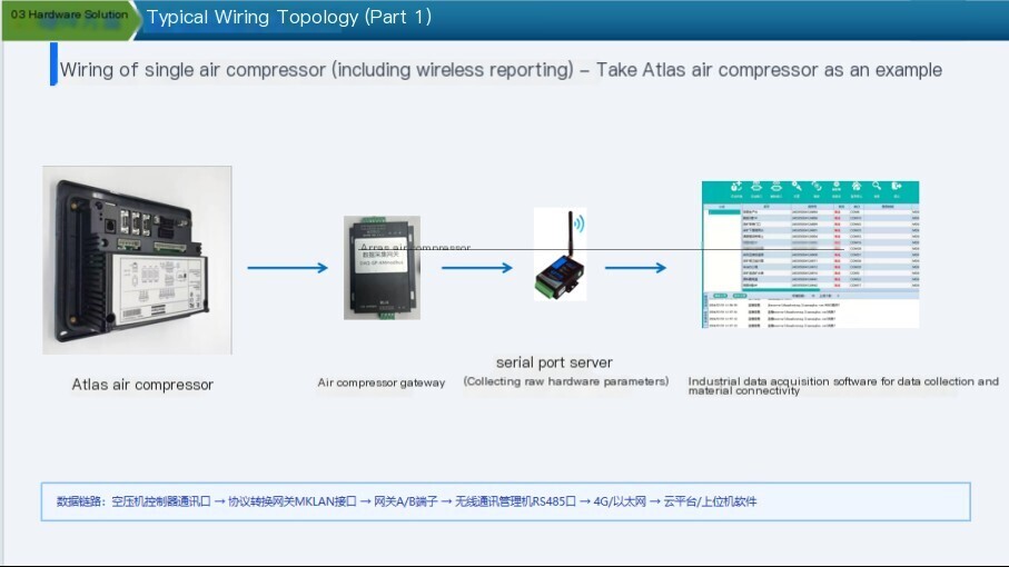
Single air compressor wiring (including wireless reporting): air compressor controller communication interface → Protocol conversionGatewayMKLAN interface →GatewayA/B terminal → wireless communication management machine/intelligent terminal RS485 interface → 4G/EthernetGateway→ cloud platform/upper computer software (take Atlas air compressor as an example).
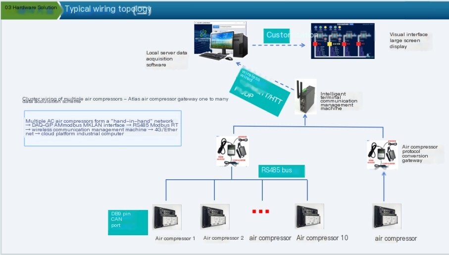
Multiple air compressor cluster wiring: Communication port of compressor controller 1 → Communication port of compressor controller 2 →... → Protocol Convert Gateway MKLAN interface → Gateway A/B terminals → Wireless communication management machine/intelligent terminal → 4G/Ethernet → Cloud platform/work control machine. Multiple AC air compressors form a "hand-in-hand" network, which is ultimately connected to the MKLAN interface of DAQ-GP AMmodbus. Gateway then sends Modbus RTU data to the wireless communication management machine/intelligent terminal via RS485 for wireless reporting.
3.5.3 Wiring precautions
The communication cable adopts shielded twisted pair, with the shielding layer grounded at one end to avoid forming a grounding loop.
Communication cables and power cables should be laid separately with a spacing of ≥ 30cm to avoid electromagnetic interference.
When multiple devices are connected in series, 120 Ω terminal resistors need to be connected at both ends of the bus to improve communication stability.
After the wiring is completed, all terminals should be checked for tightness and no looseness or short circuits.
The maximum length of the CAN bus cannot exceed 80 meters, and signals exceeding the recommended length will be accompanied by attenuation.
4、 Software functional solution
The air compressor monitoring platform supporting this scheme adopts a layered architecture design, which is divided into Data Acquisition layer, data storage layer, and application display layer. The core functions are as follows:
4.1 Data Acquisition and Storage
●Second level Real-time collection:Support the collection of all core operating parameters of the air compressor usingReal-time, with a maximum collection frequency of 1 second per time. The core collection parameters include:
Operating status: Run/Stop, Load/Unload, Manual/Automatic mode, Local/Remote control;
Process parameters: exhaust pressure, exhaust temperature, oil temperature, oil pressure, oil separator pressure difference, cooler pressure;
Equipment operation data: running time, loading time, startup times, loading times, motor speed;
Alarm fault information: comprehensive alarm, fault shutdown, emergency shutdown, motor overload, maintenance prompt;
Control instructions: Support remote start/stop, load/unload, pressure upper and lower limit settings, and other reverse control operations.
Data storage:Supports dual storage of local and cloud databases, with traceable historical data and customizable storage periods. It can store historical data for up to 5 years or more.
●Protocol Adaptation:Built in full brand air compressor library Protocol, device integration can be achieved without secondary development, supporting customized development of non-standard Protocol.
4.2 Centralized monitoring and visualization
●Overview of Equipment Status:The large screen displays the operation/stop/fault status of all air compressors, and the total number of devices, online numbers, running numbers, and fault numbers are clear at a glance.
●Real-time Data Dashboard:The details page of a single device displays all operational parameters ofReal-timein a centralized manner, supporting red alerts for parameter exceeding limits, and customizable data refresh rates.
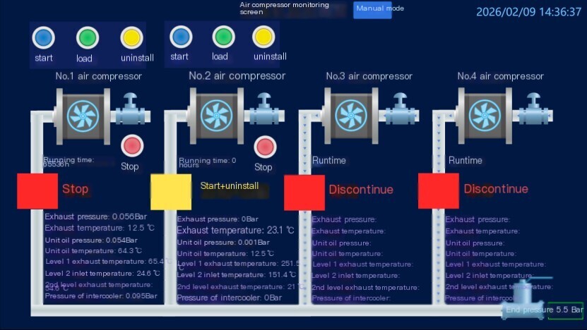
●Configuration visualization:Support customized operating process diagrams, simulate the actual operation process of air compressors, and visually display the equipment's operating status.
4.3 Intelligent Joint Control and Automation Control
●Automatic rotation operation:Multiple air compressors can be set with an automatic rotation strategy, running alternately at set time intervals (such as 6 hours/time) to balance equipment losses and extend the overall service life of the equipment.
●On demand intelligent start stop:Automatically control the start and stop of equipment based on pipeline pressure. When the pipeline pressure is below the set lower limit, the standby machine will be automatically started to supplement the pressure; After reaching the target pressure, the standby machine will automatically stop to achieve energy-saving operation.
●Automatic fault isolation:When a running device fails, the system automatically isolates it from the running queue and seamlessly switches to a backup device to ensure uninterrupted gas supply.
●Flexible control mode:Support seamless switching between manual/automatic modes. In manual mode, individual control of the start stop, loading and unloading of a single device can be achieved to meet special working conditions.
●Customization of joint control parameters:Parameters such as rotation time, upper and lower limits of pressure, and equipment priority can be flexibly configured to adapt to different on-site working conditions.
4.4 Alarm and Warning Management
●Real-time Alarm push:When the device experiences parameter overload, malfunction, shutdown, and other situations, the system immediately triggers an alarm and supports multiple alarm methods such as pop ups, sound, SMS, and WeChat push notifications.
●Alarm grading management:Support custom alarm levels, divided into general warnings, important alarms, and emergency faults according to urgency, with differentiated push strategies.
●Alarm history tracing:All alarm records are fully stored, including alarm time, alarm content, alarm level, and processing status, supporting alarm statistics and analysis.
●Preventive maintenance warning:Based on the running time and status of the equipment, maintenance reminders are automatically triggered, and the maintenance cycle can be customized, changing from "repair after failure" to "warning based maintenance".
4.5 Energy Efficiency Analysis and Report Management
●Energy efficiency analysis:Based on historical operational data, analyze the equipment's no-load rate, loading rate, and unit gas production energy consumption, identify energy-saving space, and optimize operational strategies.
●Run report:Automatically generate daily, weekly, and monthly reports, including core indicators such as device operating time, loading time, start stop frequency, energy consumption data, etc., supporting Excel/PDF format export.
●Data traceability:Support historical data trend curve query, generate trend charts by time range and parameter type for fault analysis and operation optimization.
●Third party system integration:Support integration with existing PLC, DCS, MES, ERP and other systems of users, and provide standard Modbus RTU Protocol output to achieve data interoperability.
5、 Collecting parameters and Modbus address table
Protocol Convert Gateway to open the standard register address table to the upper computer/wireless communication management computer through Modbus RTU Protocol, covering the full collection and control points of air compressor control instructions, process parameters, switch inputs, operating status, operating statistics, and pressure band settings. The upper computer/PLC/wireless terminal accesses the corresponding air compressor according to Modbus slave addresses 1-10, and the address table is uniformly applicable. The specific register address is subject to the point table document delivered with Gateway. The core acquisition parameters are described as follows:
| serial number | parameter name | visit | explanation |
| 1 | control command | RW | 1: Start up; 2: Stop; 3: Loading; 4: Uninstall |
| 2 | Reset instruction | R | 1: Fault shutdown; 2: Start up malfunction |
5.2 Process parameter category (pressure)
The data type of pressure parameters is Int16, with the unit of Bar, and the actual value is equal to the reading value multiplied by 0.001.
| serial number | parameter name | data type | explanation |
| 3 | Exhaust pressure | Int16 | Unit Bar, value x 0.001 |
| 4 | Dp oil separator | Int16 | Ditto. |
| 5 | oil pressure | Int16 | Ditto. |
| 6 | Pressure of intercooler | Int16 | Ditto. |
5.3 Process parameter category (temperature)
The unit of temperature parameters is ℃, and the actual value is equal to the reading value multiplied by 0.1.
| serial number | parameter name | data type | explanation |
| 7 | exhaust gas temperature | Int16 | Unit ℃, value × 0.1 |
| 8 | 1 # rotor exhaust temperature | Int16 | Ditto. |
| 9 | 2 # rotor inlet temperature | Int16 | Ditto. |
| 10 | 2 # rotor exhaust temperature | Int16 | Ditto. |
| 11~13 | Reserve | Int16 | Reserved extension (value x 0.1) |
| 14 | oil temperature | Int16 | Unit ℃, value × 0.1 |
5.4 Switching input category
| serial number | parameter name | explanation |
| 15 | Emergency stop input | 0: Emergency stop; 1: Normal |
| 16 | Remote start stop input | 0: Shutdown; 1: Start up |
| 17 | Remote loading and unloading input | 0: Uninstall; 1: Loading |
| 18 | Remote pressure control input | 0: On site; 1: Remote |
| 19 | Main motor overload | 0: Overload; 1: Normal |
| 20 | Fan motor overload | 0: Overload; 1: Normal |
| 21 | Motor operation feedback | 0: Stop; 1: Run |
5.5 Operating Status Category
| serial number | parameter name | explanation |
| 22 | Operating status | 1: Operation; 0: Stop |
| 23 | Add/unload status | 1: Loading; 0: Uninstall |
| 24 | Integrated Alarm | 1: Alarm; 0: Normal |
| 25 | Comprehensive fault shutdown alarm | 1: Alarm; 0: Normal |
| 26 | Comprehensive fault shutdown | 1: Shutdown; 0: Normal |
| 27 | Maintenance Tips | 1: Maintenance; 0: Normal |
| 28 | Startup failure | 1: Fault; 0: Normal |
| 29 | Emergency shutdown | 1: Emergency stop; 0: Normal |
| 30 | Hand/Automatic Adjustment | 1: Automatic; 0: Manual |
| 31 | Local/remote control | 1: Remote; 0: On site |
5.6 Running time statistics
The following parameters are stored in 32-bit dual word format, with actual values=high word x 65536+low word.
| serial number | parameter name | visit | explanation |
| 32 | Running time (high+low) | R | High character x 65536+low character, in hours |
| 33 | Loading time (high+low) | R | High character x 65536+low character |
| 34 | Number of motor starts (high+low) | R | High character x 65536+low character |
| 35 | Module communication time (high+low) | R | High character x 65536+low character |
| 36 | Loading times (high+low) | R | High character x 65536+low character |
5.7 Pressure band setting category
| serial number | parameter name | explanation |
| 37 | Pressure band selection | 1 or 2 |
| 38 | Load pressure band 1 | Unit Bar, value x 0.001 |
| 39 | Unload pressure band 1 | Ditto. |
| 40 | Load pressure band 2 | Ditto. |
| 41 | Unload pressure band 2 | Ditto. |
Note: The above point table is a general acquisition point for mainstream air compressors such as Atlas, and the specific register addresses of different brands/controller models are subject to theGatewaydocument delivered with Protocol; Non standard Protocol supports customized development.
6、 Project Implementation Case
Project Name: Atlas Air Compressor Cluster Intelligent Joint Control and Data Visualization System Project Date: January 2026
6.1 Project Background and Pain Points
There are 4 ATLAS brand air compressors in the customer's factory area (currently 2 on site, with 2 to be added later), providing a stable gas source for the production line. There are the following pain points before the renovation:
Each air compressor operates independently and relies on manual inspection to record operating parameters (pressure, temperature, etc.). The data is scattered and cannot be centrally monitored.
The start stop and rotation of equipment rely on manual labor, which poses a risk of forgetting to switch and uneven load, affecting the lifespan of the equipment.
When a device malfunctions and cannot automatically adjust its operating strategy in a timely manner, it may affect the supply of production gas sources.
Lack of historical data traceability makes it difficult to conduct energy efficiency analysis and preventive maintenance.
6.2 Project Objectives and Customization Requirements
The customer wishes to build a centralized monitoring and intelligent control system to achieve the following functions:
●Visualization in dataset:The operating status display of each unit Real-time includes operating time, inlet temperature, outlet temperature, inlet pressure, outlet pressure, oil pressure, oil temperature, etc. of the low-pressure and high-pressure engines. The controller Real-time collects and displays them on a unified large screen.
●Intelligent rotation control:Realize automatic sequential rotation operation of 4 devices, rotating every 6 hours (adjustable), with 1 device running and the other 3 turned off, balancing equipment wear and extending overall lifespan. The rotation time can be flexibly set.
●On demand intelligent start stop:Automatically control the start and stop of equipment based on pipeline pressure. When the end pressure is lower than the set lower limit (pressure can be set), the backup machine will be automatically started for replenishment; After reaching the target pressure, the original host continues to run and the backup host stops; After the main equipment malfunctions and shuts down, it will automatically kick out, while other equipment will continue to be automatically controlled in sequence to achieve energy-saving operation.
●High Availability sexual protection:When a running host fails, the system needs to be able to automatically isolate it safely from the running queue and automatically activate backup equipment to ensure uninterrupted gas supply.
●Flexible control mode:Retain manual control function, can switch between "automatic" and "manual" modes, both upper and lower pressure can be set to meet special operating needs.
6.3solution
We provide customers with a set of software Hardware integrated customization solution based on "Protocol conversion Gateway+wireless communication management machine/intelligent terminal+self-developed Data Acquisition platform+configuration visualization software":
(1) Hardware docking layer
Use Atlas air compressor Protocol to convertGateway(DAQ-GP AMmodbus), and conduct stable communication with the controller of each air compressor through the standard ModbusRTU Protocol.Gatewayis connected to the air compressor panel through the DB nine pin air compressor interface for one to many conversion and preliminary data processing. The data is then output through Modbus RTU for localData Acquisitionsystem and wireless communication management machine/intelligent terminal to read and report.
(2) Data and Logic Core Layer
Deploy the self-developed universal industrial Data Acquisition system, accurately parse equipment point tables, and achieve second level Real-time collection and storage of all air compressor parameters (while supporting various databases). The system is equipped with a custom developed integrated control logic engine, which reliably executes core control strategies such as "automatic rotation", "on-demand start stop", and "removal of faulty devices", ensuring the stability and accuracy of the logic.
(3) Application Display Layer
Tailored industrial configuration monitoring screens for customers, with intuitive design including:
●Equipment status overview:The operation/stop/fault status of the four devices is clear at a glance.
●Real-time Data Panel:Display all key temperature and pressure parameters in a centralized manner.
●Intelligent control panel:Rotation time, upper and lower pressure limits can be set, and the current host and queue order can be displayed.
●Manual control panel:Provide independent device start stop buttons and manual/automatic mode switching.
●Historical trend curve:The trend of key parameter changes can be queried at any time for fault analysis and energy efficiency management.
●Automatic alarm system:When the device is abnormal, an alarm message will pop up and be recorded.
6.4 Project Achievements
●Management visualization:The on duty personnel have a comprehensive understanding of the operation status of each air compressor at the industrial computer, bidding farewell to manual inspection and meter reading, and improving management efficiency.
●Control automation:Fully automatic rotation and on-demand start stop have been achieved, avoiding human operational errors, achieving more balanced equipment utilization, and extending the overall lifespan of the equipment.
●Energy saving operation:Accurate on-demand start stop control avoids ineffective operation and achieves significant energy-saving effects.
●System High Availability:The rapid isolation of faulty equipment and seamless replacement of backup equipment greatly ensure the stability of production gas sources and reduce the risk of unplanned shutdowns.
●Maintain digitalization:The complete operation history data provides accurate data support for preventive maintenance of equipment, transforming "repair after failure" into "warning based maintenance".
7、 Application value and benefits
This plan has been implemented and verified on multiple industry sites, with significant comprehensive benefits. The core application value is shown in the table below:
| value dimension | Pain points before renovation | Empowering the plan | expected benefits |
| Management Efficiency | Manual inspection and meter reading, scattered data, unable to centrally grasp equipment status | Centralized visualization of the configuration screen, Real-time displays the operating status of all air compressors in the factory | Significant improvement in management efficiency, bidding farewell to manual meter reading |
| Equipment lifespan | Start stop rotation relies on manual labor, resulting in uneven load and imbalanced equipment wear and tear | Automatic sequential rotation, balanced equipment operating time, automatic isolation of faulty equipment | More balanced utilization of equipment, extending overall service life |
| energy conservation and consumption reduction | Invalid operation of equipment, mismatch between gas supply and demand, high energy consumption | On demand intelligent start stop, precise control of pipeline pressure, avoiding empty load waste | Achieve significant energy-saving effects and reduce energy consumption per unit of gas production |
| stable operation | The malfunction cannot be adjusted in a timely manner, affecting the supply of production gas source | Fault automatic isolation+seamless replacement of backup equipment, guaranteed byHigh Availability | Reduce the risk of unplanned shutdowns and ensure stable gas supply |
| Maintenance Method | Repair after malfunction, lack of data support, passive maintenance | Complete storage of historical data during operation, triggering preventive maintenance reminders | Change from 'repair after malfunction' to 'early warning maintenance' |
| data asset | Without historical data traceability, it is difficult to conduct energy efficiency analysis | Historical data can be traced back more than 5 years, supporting energy efficiency analysis and reporting | Data driven operation optimization and decision-making |
| system integration | The data islands of each system make it difficult to interconnect and communicate with each other | Standard Modbus RTU output+wireless terminal multi Protocol reporting, compatible with PLC/DCS/cloud platform | Realize data interoperability and support digital transformation |
8、 About Us
Shanghai DAQ-IoTNetwork Technology Co., Ltd. is a professional service provider in the industrial field ofData Acquisition, focusing on the research and implementation ofData AcquisitionandProtocolconversion, centralized monitoring, and intelligent control of industrial equipment such as air compressors. The company's mission is to make every industrial equipment intelligent and controllable. It has independently developed a series of air compressors Protocol conversion and acquisition Gateway, wireless communication management machines/intelligent terminals, and a general industrial Data Acquisition platform. TheProtocollibrary has been adapted to more than 190 controller models, covering mainstream air compressor, centrifuge, and supporting equipment brands at home and abroad.
We solemnly promise that you are not only purchasing products, but also providing meticulous and thoughtful technical support services. The conversion fromProtocoltoGatewayonly requires ordinary workers to connect and install it on site, without the need for debugging; We provide free remote guidance, remote configuration and debugging services, and send data to the user's designated cloud platform. As an industrial expert inData Acquisition, Shucai IoT provides free consulting services forIoTsolutions.


评论
发表评论