B83 Dynamic Ring IoT Gateway BOX-DS-B83-MB0402scada Graphic Configuration Gateway Rack mounted
As a professional provider of IoT data acquisition solutions and an expert in industrial IoT data acquisition, the editor of Shanghai Data Acquisition IOT Technology Co., Ltd, (daq-iot) hereby presents the following introduction, and sincerely welcomes discussions and exchanges. Supported Communication Interfaces: CAN, RS485, Mbus, 4–20mA, Profibus, CC-Link, HART, digital I/O, etc. Industrial Protocols: Modbus RTU/TCP, HJ212, IEC104, DLT645, DLMS, IEC61850, MQTT, etc. Mail:export@daq-iot.com
DS-B83-MB0402
B83 Dynamic Ring IoTGatewayBOX
Hardware Specification]
RS485/RS232 interface: 2-channel RS485, supports switching RS232
Switching input (DI): 4 channels
Switching output (DO): 2 channels
Analog input (4-20 mA current or 0-5 V voltage): 4 channels, multiplexed with switch input (DI)
External power supply interface: 3-channel DC12V, maximum power of 12W
Network interface: 5 RJ45 10M/100M adaptive Ethernet ports
Other interfaces: 1 x USB 2.0
[Product Performance]
Sensor Access performance: 4-channel switch signal equipment access, supporting switching to analog input; Each serial port supports 8Sensor, totaling 16Sensor; The total number of connected data (Sensor) is 1000
[Product Features]
Support dual network
Supports Modbus TCPModbus RTU、DLT645、 CJT188、BACNet、 IEC104 and other standards Protocol
Supports over 450 third-party devices to access Protocol, involving southbound collection of Protocol from UPS, Sensor, etc
Support standard Modbus Protocol custom configuration import
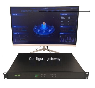
DAQ-GP-GCGW SCADA Graphics Configuration Gateway is a high-performance processor with a clock speed of up to 2.0GHz and a 64 bit quad core Arm ® Cortex ®- The A55 architecture integrates multiple powerful embedded Hardware engines such as G52 GPU and NPU with 1TOPs computing power, providing excellent performance for high-end display and control applications. In order to meet the application needs of different display and control products, DAQ-GP-GCGW has designed RS-485, RS232, USB, Ethernet, DI, DO, Vout, HDMI, etc. on the Hardware interface. The built-in SATA interface can expand SSD solid-state Hardware and PCIe interface to adapt to 4G modules, meeting the access needs of various communication methods of AIoT products. The device supports up to 16 serial port connections. Gateway is embedded with our self-developed universal industrial Zhihu system, which flexibly realizes Real-time data upload and reception. It supports custom configuration of large screen screen design, allowing industrial data to be viewed at a glance. In addition, the device is equipped with USB storage, USB Debug port, and USB-D upgrade port to meet the on-site FOTA, debugging, data storage, and data export application functions of the product.
| name | Communication Management Machine DAQ-GP-GCGW |
| processor | Four core Cortex-A55, with a maximum frequency of 2.0GHz |
| GPU | ARM G520 |
| NPU | 1TOPS* RKNN |
| RAM capacity | 4GB |
| FLASH capacity | 32G |
| RTC | Built in RTC, RTC timing function |
| DI | 18 way DI photoelectric isolation, dry contact input |
| DO | 4-channel DO relay |
| VOUT | 4-channel power output DC 12V (maximum 12V 2A) |
| RS485 | 16 RS485 interfaces (including 8 SPI to RS485 interfaces) default baud rate 9600 |
| RS232 | 2-channel independent isolation default baud rate 115200 (multiplexed RS485) |
| USB | 2-channel USB 2.0 |
| Ethernet port | 4-channel 2x10/100M/2x100/1000M adaptive network port (independent IP, different network segments) |
| 4G function | All network 4G-CAT1 |
| SIM card | 1 self-locking SIM interface |
| SSD hard drive | MSATA supports a maximum of 2TB |
| SD card | TF (128GB Max) |
| Power failure protection | Support (5-10 seconds) |
| software watchdog | support |
| indicator light | 5 customizable and controllable channels |
| buzzer | 1 supports custom Buzzer |
| Type-c | 2-channel 1 * OTG upgrade, 1 * USB debugging port |
| video output | HDMI |
| power input | AC90-220V dual power supply |
| Operating Temperature | Working temperature -20~+55 ℃ |
| Ambient temperature and humidity | Working humidity: 5% -95% (no condensation) |
| operating system | Ubuntu20.04 |
| Shell and installation | Sheet metal shell -1U; |
| Software Protocol | Support providing secondary development interface Protocol, calling various interface functions of the all-in-one machine |
Table 1 Product Configurationtable
Gatewayadopts advanced highly integratedHardwareand software platform to optimize many commonly usedIoTplatforms, completing functions such as wireless reception, transmission, processing, and parsing. The structural size ofGatewayis 483 * 330 * 32mm. It can be widely used in variousIoTfields, such as industry, smart agriculture, power monitoring, environmental pollution monitoring, etc. The sentence is: Smart Home、 Scenarios such as security management.
1 Service Philosophy
Our company solemnly promises:
You are not only purchasing products, but also providing meticulous and thoughtful technical support services!!!( =^_^= )
This product only requires ordinary workers to connect and install it on site! No debugging required!
We provide free remote guidance, remote configuration and debugging services, and send data to the user's designated cloud platform.
Free consultation service forIoTsolution!
2 Feature Introduction
3.1 General Industrial Data Acquisition System
Connect the device through the network port and use the ping command to test whether it is in the same network segment as the local device or directly connect to the display screen using HDMI. After opening the device, you can open a browser and input:192.168.10.2:16801/scada/(The red address in front needs to be filled in with the IP address of the corresponding network port. Please refer to "Table 3 Network Port Description Diagram" below for the corresponding IP address.); If using HDMI to connect to the display screen for direct debugging, enter the website address:http://localhost:16801/scada/ Or click on the website on the system desktop to open the login interface of the Universal Industrial Data Acquisition system;
Enter account: super Initial password: 123456 to log in to the system;
This system is a set of equipment and management software running onGateway, mainly used for data collection, control, storage, query, display, and upload of various instruments and equipment (PLC, injection molding machine, CNC machine tool, electric meter, flowmeter, analyzer, etc.). The main functions of the system include:
Figure 3 Example diagram of the general industrial Data Acquisition system interface
U device Data Acquisition, upload platform data, and communication Protocol conversion.
U supports a wide range of data links and communication Protocol.
Flexible and easy-to-use transmission configuration.
U data Real-time monitoring and alarm monitoring.
Diversified data storage and querying, supporting database upload.
Free configuration and visual interface design.
User and permission management, allowing users to freely create and manage downstream accounts.
The U interface supports multiple languages.
3.2 Communication Protocol Support
The supported communication links include:
| Link type | communication link |
| TCP | TCP Client |
| TCP server | |
| serial port | Serial UART |
| UDP | UDP |
| HTTP | HTTP server |
| HTTP client | |
| OPC | OPC-UA |
| OPC-DA | |
| MQTT | MQTT-TCP |
| MQTT-WebSocket |
The supported communication links Protocol include:
| Protocol Type | Main Protocol | Child Protocol |
| PLC communication Protocol | Modbus | Modbus-RTU |
| Modbus-TCP | ||
| Modbus-ASCII | ||
| Siemens S7 | ||
| Mitsubishi MELSEC Communications Protocol | MELSEC-1E | |
| MELSEC-3C | ||
| MELSEC-3E | ||
| MELSEC-4C | ||
| MELSEC-4D | ||
| Mitsubishi-Fx | ||
| OPC Communication Protocol | OPC-UA | |
| OPC-DA | ||
| MQTT communication Protocol | MQTT-JSON | |
| Instrument communication Protocol | DL/T645 | |
| DL/T698.45 | ||
| DLMS | DLMS-LN | |
| DLMS-SN | ||
| IEC62056-21 | ||
| Edmi Command-Line | ||
| CDT | ||
| IEC103 | ||
| IEC104 | ||
| Environmental Monitoring Communication Protocol | HJ212 | Data Transmission Standard for Pollution Source Online Automatic Monitoring System |
| SL651 | Hydrological Monitoring Data Communication Protocol | |
| ZY206 | (SZY206-2016) Water Resources Monitoring Data Transmission Protocol |
3.3 Configuration Visualization Interface
Figure 4 Example of Configuration Screen
On the configuration page, the available functions include:
Display the device values collected by Real-time.
Display data history.
Display the system process of dynamic changes.
U issues instructions and values to the device by manipulating page elements.
Switch to a different view page.
3 Interface Definition
Figure 5 Gateway Interface Definition Diagram
The DAQ-GP-GCGW graphic configuration Gateway is designed to maintain a clear and concise style. The serial port function interface is as follows:
| function | name | explanation | Mapping |
| serial port | A1 B1 | 485 serial port 0 | /dev/ttyS0 |
| A2 B2 | 485 serial port 1 | /dev/ttyS1 | |
| A3 B3 | 485 serial port 3 | /dev/ttyS3 | |
| A4 B4 | 485 serial port 4 | /dev/ttyS4 | |
| A5 B5 | 485 serial port 5 | /dev/ttyS5 | |
| A6 B6 | 485 serial port 7 | /dev/ttyS7 | |
| A7 B7 | 485 serial port 8 | /dev/ttyS8 | |
| A8 B8 | 485 serial port 9 | /dev/ttyS9 | |
| RX9 TX9(A9/B9) | 232 serial port 6 | /dev/ttyS6 | |
| TX10 RX10(A10 B10) | 232 serial port 0 | /dev/ttyS0 | |
| SPI to serial port conversion | A9 B9 | 485 serial port | /dev/ttysWK0 |
| A10 B10 | 485 serial port | /dev/ttysWK1 | |
| A11 B11 | 485 serial port | /dev/ttysWK2 | |
| A12 B12 | 485 serial port | /dev/ttysWK3 | |
| A13 B13 | 485 serial port | /dev/ttysWL0 | |
| A14 B14 | 485 serial port | /dev/ttysWL1 | |
| A15 B15 | 485 serial port | /dev/ttysWL2 | |
| A16 B16 | 485 serial port | /dev/ttysWL3 |
Table 2 Serial port pin list
The DAQ-GP-GCGW graphic configuration Gateway includes 4 network ports, and the interface description is as follows:
| function | name | explanation | Mapping |
| Ethernet port | Eth1 | 1000M default IP: 192.168.10.2 | eth0 |
| Eth2 | 1000M default IP: 192.168.20.2 | eth1 | |
| Eth3 | 10/100M default IP: 192.168.30.2 | eth20 | |
| Eth4 | 10/100M default IP: 192.168.40.2 | eth30 |
Table 3 Network Port Description Table
In addition, the device also supports RS232, USB, DI, DO, and Vout interfaces. For specific interface definitions, please contact our company for detailed product technical documentation;
4 Gateway Size
Figure 6 Gateway Dimensional Diagram
| parameter | description | |
| mechanical parameters | Dimensions (mm) | 483*330*32mm |


评论
发表评论