Based on DAQ for IIOT scada Universal Industrial Data Acquisition System Intelligence Platform and Zhihu IoT Application Case in Automotive Parts Coating Line
As a professional provider of IoT data acquisition solutions and an expert in industrial IoT data acquisition, the editor of Shanghai Data Acquisition IOT Technology Co., Ltd, (daq-iot) hereby presents the following introduction, and sincerely welcomes discussions and exchanges. Supported Communication Interfaces: CAN, RS485, Mbus, 4–20mA, Profibus, CC-Link, HART, digital I/O, etc. Industrial Protocols: Modbus RTU/TCP, HJ212, IEC104, DLT645, DLMS, IEC61850, MQTT, etc. Mail:export@daq-iot.com
based onDAQ for IIOT SCADA Universal Industrial Data Acquisition System Digitized platform and DAQ-IOT IoT Application Case in Automotive Parts Coating Line
- System Overview
This technical solution is a digital system designed byShanghai DAQ-IoTTechnology Co., Ltd. for the painting production line and related equipment of automotive parts factories. The purpose is to collect, record, and generate a historical database of the operational data Real-time of relevant equipment online; Through the intelligent analysis module, data is calculated, statistically analyzed, and a device operation report is generated (presented in the form of charts and graphs during operation)

Report on maintenance and repair recommendations for equipment, including maintenance records, energy consumption, operational efficiency and economy, equipment condition, equipment prevention, prediction, and conditions; Manage the equipment withO&M, provide guidance manuals, operation videos, and other materials required for equipment operation, maintenance, and repair, and guide and assist maintenance personnel in completing equipment maintenance and repair; The platform publishes device operation data through an intuitive and user-friendly interface Real-time. Authorized users can access the platform at any time to view system Real-time data, reports, curves, reports, and alarm information; The platform actively sends system prompts, warnings, alarms, and other information to the preset mobile phone number. The staff can timely obtain the operating status, equipment condition, and abnormal situations of the equipment, predict hidden equipment failures, arrange equipment maintenance and repair plans in advance, and avoid losses caused by unexpected equipment failures and shutdowns.
According to the conventional design, the data required to be collected for painting and related equipment is as follows:
Fan monitoring: A set of fans is used as an independent monitoring object to collect power consumption data (current, voltage, power, electrical energy) of the fans, as well as vibration and temperature of the fan equipment itself. Fans with lower power may not collect temperature or vibration data, or only collect temperature or vibration data depending on the specific situation. Fan, with primer, color paint, gloss paint and brand new air supply fan; Exhaust fans for pre-treatment, anti-static chamber, primer, color paint, gloss paint spraying room, etc; Environmental protection equipment exhaust fan and drying furnace circulating fan.
Water pump monitoring: A water pump serves as an independent monitoring object, collecting electricity data (current, voltage, power, electrical energy) of the water pump, as well as vibration and temperature of the water pump motor body. Motors with lower power may not collect temperature or vibration data, or only collect temperature or vibration data depending on the specific situation. Water pump, a circulating water pump for spray rooms with primer, color paint, gloss paint, etc; Water pumps for water curtain towers with primer, color paint, gloss paint, etc; And the circulating water pump for the chiller water tank.
Electric heating monitoring: Monitor the electricity consumption data, current, voltage, power, energy, and harmonics of each electric heating point before and after the fresh air, each electric heating point of the circulating air, and the electric heating point of the preheating furnace.
Conveyor belt monitoring: Collect electrical data of conveyor belts, elevators, rollers, and other equipment on each production line, with a focus on current, voltage, and power, to monitor whether the relevant equipment is operating normally.
Differential pressure and cleanliness monitoring: Differential pressure monitoring of primer, color paint, gloss paint, and fresh air supply boxes, monitoring of differential pressure data at three locations: initial, medium, and high efficiency for each supply box; Pre treatment room, anti-static room, primer, color paint, gloss paint, etc. spraying
Wind pressure monitoring and indoor cleanliness monitoring at the entrances and exits of rooms and waiting rooms.
Temperature and humidity monitoring: pre-treatment room, anti-static room, spray booth for primer, color paint, and gloss paint, primer, color paint, and topcoat, etc
Monitoring of environmental temperature and humidity in paint supply rooms, blending rooms, and other locations.
Combustible gas monitoring in spray painting rooms and their passages.
Monitoring of freezer and freezer water tank: monitoring the operating status, electricity and water consumption of the freezer; Monitor the water temperature and pressure at the inlet and outlet of the chiller water tank.
PH value monitoring: Monitor the pH value of the circulating water tank.
Drying furnace monitoring: Monitor the temperature inside the drying furnace and collect temperatures in the low, medium, and high temperature zones.
Distribution system monitoring: Monitor the electricity consumption data of the workshop and painting production line's incoming and outgoing circuits. For high-capacity circuits, such as incoming and outgoing circuits with high loads, increase temperature monitoring; Monitor the electricity consumption data of environmental protection cabinets.
Steam pipeline monitoring: Monitor the pressure and temperature of steam, as well as the flow rate of steam to the main pipelines of each coating line.
Monitoring of air compression equipment: monitoring the operating status, electrical data, and compressed air flow rate of the air compressor (collected from the outlet end of the storage tank).
2. Scheme Design Description
The design of the digital system scheme for the painting line is as follows:
Designed with a layered and distributed structure, based on a simpler, more stable, and reliable communication network, the system is more flexible, compatible, and scalable. The system is divided into three layers: digital platform, communication network, and signal data acquisition
Structure. The digital platform consists of cloud servers (Private CloudorPublic Cloud)DAQ for IIOT scadaGeneral Industrial Data Acquisition System Software Composition; The communication network consists of IoT gateway, wireless communication terminals, local area network, and the Internet; Signal data acquisition is carried out by a wireless acquisition moduleSC-GP-EM4GIt consists of wireless power monitoring instruments, wireless intelligent Sensor, and so on.
The project implementation is simpler and more convenient, with lower construction costs and a shorter construction period for daq iot data acquisition IoT. Whether it is adding monitoring equipment to existing production equipment or adding Data Acquisition to new lines, project implementation is very simple, convenient, and economical. Choose wireless communication to transmit data, and for monitoring points with inconvenient power supply, choose battery powered Sensor and collectors to avoid the troubles caused by cable laying; Electricity consumption Data Acquisition, choose a multi circuit power monitoring meter, and equip it with RS485 open type current transformers to avoid disassembling cables and copper bars in the original distribution cabinet, and to not increase the design and production difficulty of the new distribution cabinet, greatly reducing construction costs and construction period; Signal acquisition or data reading, if there are already monitoring points on the original equipment, signals can be collected from the original Sensor or data can be read from the collector to reduce construction costs and difficulties, without causing any impact on the original system.
The DAQ for IIOT scada general industrial Data Acquisition system digitalization software is the brain of the system; Read data from communication networks, generate databases, calculate, analyze, report, and publish data. Especially utilizing intelligent analysis to provide users with more conventional Data Acquisition
Provide greater value to customers with data, information, and reports that the system cannot provide.
The system design has rich communication interfaces and communication Protocol for exchanging data with other systems. The system can exchange data with other systems or devices, such as MES, SCADA general industrialIoTsystems, DCS systems, as well as PLCs, equipment control units, etc., through digital platforms,IoTswitches, wireless communication terminals, and other devices.
Better and more convenient scalability: The reduction or cancellation of monitoring points will not cause any inconvenience to the system or any other monitoring points; The addition of monitoring points can be directly connected to existing IoT switches or wireless communication terminals
End, forward data to the platform; For scenarios with a large number of monitoring points or locations further away from existing monitoring points, while adding monitoring points, IoT or wireless communication terminals should be added to connect the terminals to the communication network platform. The system is not affected by the number of monitoring points or the number of communication network devices.
System schematic diagram:
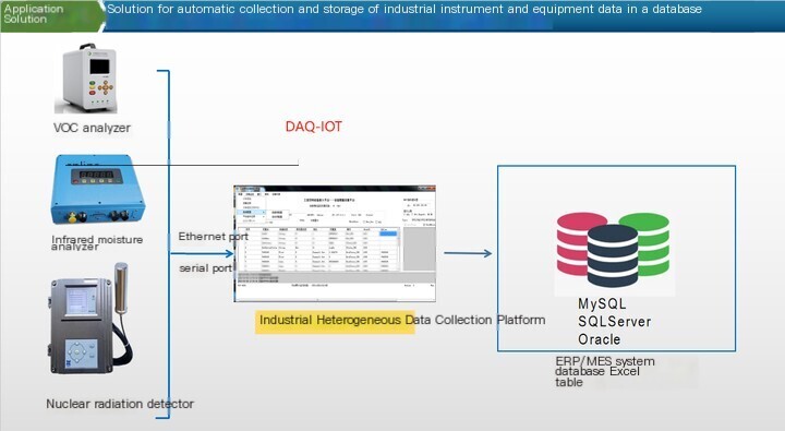
System Description:
Digital platform software that can be deployed on users' servers; Users of daq iot data acquisition platformIoTcan also rent theShanghai DAQ-IoTdigital view cloud platform, saving them the trouble of building their own platform and subsequent maintenance.
IoTis a terminal that supports uploading data to digital platforms via Ethernet, Wi Fi, and 4G/5G. It also supports various communication methods such as MQTT, SOAP, and databases, and can be connected to third-party platforms for communication.
The node consists of Sensor and a collection module. The node device uploads data to the IoT gateway or terminal through LoRaWAN.
Node installation also directly reads and collects existing data and signals on site, and uploads them wirelessly.
3. Design of signal and data acquisition scheme
Plan description, arranged and organized according to data categories and collection methods.
3.1 Electricity collection plan
There are two ways to obtain electricity data to choose from. For monitoring points without power monitoring meters or with meters but no signal output, install a new SC-GP-EM4G wireless power monitoring device to collect power consumption data of various distribution circuits or equipment, such as fans, water pumps, environmental protection equipment, distribution cabinets, as well as electric heating, conveyor belts, etc; For power monitoring meters that are equipped with
RS485 output data, select DAQ-GP IOTGateWay serial wireless conversion module, read data from the original power monitoring table and upload it.
SC-GP-EM4G Wireless power monitoring device:
The SC-GP-EM4G wireless power monitoring instrument adds LoRa communication method on the basis of traditional multifunctional power instruments,
Implement electricity Data Acquisition and wireless transmission. Measure full power parameters such as current, voltage, energy, compound rate, and energy quality, monitor power consumption data for 1 to 4 distribution circuits, and can be equipped with open-loop current transformers.
Technical Details
Measurement function:
| Real-time Measurement | Three phase current, three-phase voltage, line voltage, active power, power factor, system frequency, no power, apparent power |
|---|---|
| electricity metering | |
| active energy | Total active power, forward active power, reverse active power, and compound rate power (peak, off peak, off peak, and off peak) |
| Reactive energy | Total reactive power, forward reactive power, reverse reactive power, and compound rate power (peak, off peak, off peak, and off peak) |
| Multiple rate electricity | The time-sharing active, reactive, and apparent energy metering function accumulates and stores total, peak, off peak, and valley energy according to the corresponding time periods. The maximum number of time zones per year is 14, and each time zone table can have up to 8 daily time zones, with a maximum of 14 daily time zones; The minimum interval between time periods is 15 minutes and should be greater than the demand cycle set in the energy meter; The time period can be set across zero points. |
| power quality | |
| harmonic | Harmonic distortion rate of 2-31st order of three-phase voltage, total harmonic distortion rate of each phase voltage, harmonic distortion rate of 2-31st order of three-phase current, total harmonic distortion rate of each phase current |
| unbalance ratio | Voltage imbalance rate, current imbalance rate |
|---|---|
| demand | |
| demand | Measurement of active and reactive power demand, measurement of maximum active and reactive power demand; The default demand interval is 15 minutes, using a slider method; |
| Maximum demand record | Store the maximum demand data for active and reactive power over the past 12 months, as well as the time of occurrence of the maximum demand |
| Historical data storage | |
| historical electricity | Freeze data on a monthly basis, with a default freezing time of 0:00 on the 1st of each month. Freeze data (including combined active energy, forward active energy, reverse active energy, combined reactive energy 1, combined reactive energy 2, four quadrant reactive energy, forward apparent energy, reverse apparent energy, and phase wise total energy) to store the historical electricity consumption of the past 12 months. |
| Freeze the whole point | Freeze data on an hourly basis, with a freezing interval of 15 minutes. Freeze data (including freezing time, combined active total energy, reactive total energy, forward active total energy, reverse active total energy, combined reactive 1 (forward reactive) total energy, and combined reactive 2 (reverse reactive) total energy) to store data from the last 30 days. |
measurement accuracy
| parameter | Precision | measurement range | parameter | Precision | measurement range |
|---|---|---|---|---|---|
| current | Level 0.5 | 0.01Ib~1.2Imax | power | Active power level 1, reactive power level 2 | |
| voltage | Level 0.5 | AC10V~300V | harmonic | Voltage harmonic level I, current harmonic level I | 2-31 times |
| frequency | ±0.02Hz | 45Hz~60Hz | electric energy | Active power level 1, reactive power level 2 | |
| power factor | ±0.02 | 0~±1.0 |
Specifications
| Reference voltage (Un) | 3×220/380V | Voltage circuit power consumption: ≤ 0.2VA (per phase) | ||
|---|---|---|---|---|
| Reference current | 3×1.5(6)A | 3×20(100)A | 3×50(200)A | Current circuit power consumption: ≤ 0.4VA (per phase) |
Other parameters
| LoRa | frequency band | Frequency band: 400-510MHz, 863-928MHz; Supply according to the frequency bands specified in different regions. |
|---|---|---|
| communication parameters | Transmission power: 20dBm, 100mW; Receiver sensitivity: -148dBm. | |
| transmission distance | The ideal transmission distance is 15Km; the transmission distance in factory environment is 300m to 5Km, which is greatly affected by geographical environment. | |
| power supply | Input: AC85V~AC265V, 50/60Hz or DC100V~DC330V; Maximum power consumption: ≤ 2W. | |
| Overall dimensions | 100mm *72mm * 70mm。 |
DAQ-GP-IOTGateWay Serial wireless conversion module:
DAQ-GP IOTGateWay serial wireless conversion module, [daq iot data acquisition IoT, enables RS485 interface devices to wirelessly access IoT through LoRa. Used for electric meters PLC、 Wireless access to temperature controllers, frequency converters, equipment control units, and other devices IoT. Easy to install and use, with lower costs. One DAQ-GP IOTGateWay wireless conversion module can connect multiple 485 devices for networking.
technical parameter
| LoRa | frequency band | Frequency band: 400-510MHz, 863-928MHz; Supply according to the frequency bands specified in different regions. |
|---|---|---|
| communication parameters | Transmission power: 20dBm, 100mW; Receiver sensitivity: -148dBm. | |
| transmission distance | The ideal transmission distance is 15Km; the transmission distance in the factory environment is 300m to 5Km, and the geographical environment has a significant impact. | |
| RS485 | Data bits: 7, 8; Stop position: 1, 2; Check bits: None, Even, Odd; Baud rate: 1200 bps~115200Kbps; | |
| power supply | Working voltage: DC6-24V; Maximum power consumption: ≤ 0.5W. | |
| Overall dimensions | 36mm *95mm * 95mm。 |
List of electrical collection equipment:
| serial number | Product Name | Equipment model and specifications | unit | quantity | Description of monitoring points |
|---|---|---|---|---|---|
| 1 | Wireless power monitoring device | SC-GP-EM4G | block | 1 | Air supply fan |
| 2 | Wireless power monitoring device | SC-GP-EM4G | block | 1 | Exhaust fan |
| 3 | Serial wireless conversion module | DAQ-GP-IOTGateWay | platform | ||
| 4 | platform | ||||
| 5 | platform |
3.2 Temperature and vibration Data Acquisition scheme
For rotating equipment such as fans and pumps, a simpler and more direct method is to use daq iot data acquisition IoT to monitor the vibration and temperature data of the equipment body. When the equipment malfunctions, it can be quickly and sensitively detected.
choice DAQ-LP-VTLORA/4G temperature vibration Sensor, detecting temperature and vibration data of fans, water pumps, and motors. Sensor is installed in
On the motor body or bearing seat, threaded fixation or magnet fixation can be selected for installation. The ideal battery life is over 5 years.
Sensorcan also monitor temperature vibrations of equipment such as pipelines and tanks.
Technical parameters:
| LoRa | frequency band | Frequency band: 400-510MHz, 863-928MHz; Supply according to the frequency bands specified in different regions. |
|---|---|---|
| communication parameters | Transmission power: 20dBm, 100mW; Receiver sensitivity: -148dBm. | |
| transmission distance | Ideal transmission distance, 1km; factory environment transmission distance, 100 to 300m, with significant geographical impact. | |
| Vibration technical parameters | Vibration: Acceleration rate (peak), true effective value (RMS); Measure the vibration of X, Y, and Z axes; Measurement range: Acceleration rate 0 to 130 mm/s, speed 0 to 20 mm/s; Monitoring frequency band: 10 to 1000 Hz (± 3 dB); Measurement accuracy: ± 10% FS @ 100 Hz (X, Y, Z axis), ± 20% FS @ 100 Hz (3D synthesis). | |
| temperature | Media: gas, liquid, solid, contact type. Range: -20 ℃~300 ℃, can be provided according to user requirements; Accuracy: AA level. Sensor Material: 304, 316, Sensor Type: PT100, PT1000, Cu50, as well as N, S, J, K type thermocouples; Sensor The probe shape and size are designed and produced according to the requirements. | |
| power supply | Built in battery power supply; Sleep current<5 µ A; maximum power consumption<0.5W. | |
| size | ≤Ø50mm * LoRaWANmm。 |
List of temperature and vibration collection equipment:
| serial number | Description of monitoring points | Equipment model and specifications | unit | quantity | Remarks |
|---|---|---|---|---|---|
| 1 | Air supply fan | DAQ-LP-VTLORA/4G16BC | platform | ||
| 2 | Spray room circulating water pump | DAQ-LP-VTLORA | platform | ||
| 3 | Water curtain tower water pump | DAQ-LP-VTLORA/ | platform | ||
| 4 | platform | ||||
| 5 | platform |
3.3 Environmental parameter collection plan
Environmental parameters, monitoring temperature, humidity, cleanliness, wind speed, pressure difference [daq iot data acquisition IoT, as well as toxic and harmful gas concentration data.
3.3.1 Temperature and humidity collection
The temperature and humidity of the workshop environment, working environment, and hanging spaces above and below.
Technical details:
choice DAQ-LP-GWTH Explosion proof wireless temperature and humidity monitoring system Sensor, used to monitor the temperature and humidity in pre-treatment rooms, anti-static rooms, spray rooms, paint supply rooms, blending rooms, and other spaces; Select DAQ-GP-GWTH wireless temperature and humidity Sensor to monitor normal
| product | DAQ-LP-GWTH | |
|---|---|---|
| Temperature and humidity parameters | Temperature range: -40~120 ℃, accuracy: ± 0.3 ℃; Humidity range: 0-100% RH accuracy: ± 3% RH. | |
| Communication parameters | Communication method: LoRa; Frequency band: 400-510MHz, 863-928MHz; Supply according to the frequency bands specified in different regions. Transmission power: 20dBm, 100mW; Receiver sensitivity: -148dBm. S485,A,B,GND; Communication distance: ideal 15Km; factory environment transmission range of 300m to 5Km, with significant geographical impact. | |
| working voltage | DC6-24V, Power consumption<0.5W, sleep current<20 µ A. |
3.3.2 Differential pressure and wind speed collection
Select DAQ-GP-GWAD wireless pressure difference Sensor and DAQ-GP-GWAS wireless wind speed Sensor, and collect pressure difference and wind speed respectively.
Monitor the pressure difference at the initial, intermediate, and high-efficiency positions of the air supply box for primer, color paint, gloss paint, and fresh air; [daq iot data acquisition IoT monitors the pressure difference at the entrances and exits of pre-processing rooms, anti-static rooms, spray rooms, etc. Monitor the wind speed of the air duct and select monitoring points according to on-site requirements.
Technical details:
DAQ-GP-GW series wireless Sensor, designed according to low-power and battery powered standards, with display. Especially for measuring wind speed in ducts, there is no need to insert any accessories into the ducts, and the installation and wiring are simple and convenient, meeting more application scenarios.
| product | DAQ-GP-GWAD | DAQ-GP-GWAS |
|---|---|---|
| monitoring parameters | Pressure difference: 0~± 250Pa, accuracy: 0.5%. | Wind speed: 0-40 meters per second, accuracy: 0.5%. |
| Communication parameters | Communication method: LoRa; Frequency band: 400-510MHz, 863-928MHz; Supply according to the frequency bands specified in different regions. Transmission power: 20dBm, 100mW; Receiver sensitivity: -148dBm. S485,A,B,GND; Communication distance: ideal 15Km; factory environment transmission range of 300m to 5Km, with significant geographical impact. | |
| working voltage | Working voltage: DC5V; Maximum power consumption: ≤ 0.5W. Optional external battery pack power supply. | |
| Product dimensions | LoRaWANmm *60mm * 35mm。 |
3.3.3 Cleanliness collection
Technical details:
Monitor the cleanliness (suspended particles) data of pre-treatment rooms, anti-static rooms, spray rooms, and other spaces. Select DAQ-GP-GWPC wireless particle counter to collect cleanliness data of the corresponding space.
| product | DAQ-GP-GWPC wireless particle counter |
|---|---|
| measurement parameters | Self purification time ≤ 10 minutes; Repeatability ≤ 10% FS; Particle concentration indication error ≤ ± 30% FS; Measurable particle size, 0.3, 0.5, 1, 3, 5, 10 μ m, divided into 6 particle size channels, maximum measurable particle concentration: ≤ 38K particles/L. |
| Communication parameters | Communication method: LoRa; Frequency band: 400-510MHz, 863-928MHz; Supply according to the frequency bands specified in different regions. Transmission power: 20dBm, 100mW; Receiver sensitivity: -148dBm. S485,A,B,GND; Communication distance: ideal 15Km; factory environment transmission range of 300m to 5Km, with significant geographical impact. |
| working voltage | AC220V 。 |
3.3.4 Gas concentration monitoring
Select DAQ-LP-GWGX wireless gas Sensor to monitor the concentration of combustible gases in painting lines, spray booths, passages, and other places and spaces.
DAQ-LP-GWGX Wireless gas Sensor,Developed, designed, and produced according to explosion-proof standards, integrating sensing components, information processing, and wireless communication to monitor gas concentration in the environment.
Installed in environments that require monitoring of gas concentration, detecting the presence of toxic and harmful gases, leaks, or exceeding certain gas concentrations.
Wireless gas Sensor with display, sound and light alarm, and output 1 DO (relay contact) to other systems such as fire protection.Detailed parameters:
| product | DAQ-LP-GWGX Wireless Gas Sensor |
|---|---|
| Gas parameters | Combustible gas: detection principle: catalytic combustion/infrared absorption; Range: 0-100% LEL; Accuracy: ± 5%; Repeatability: ≤± 2%; Response time: TLoRaWAN ≤ 25S; Sensor lifespan:>3 years (catalytic combustion); >5 years (infrared absorption). |
| Communication parameters | Communication method: LoRa; Frequency band: 400-510MHz, 863-928MHz; Supply according to the frequency bands specified in different regions. Transmission power: 20dBm, 100mW; Receiver sensitivity: -148dBm. S485,A,B,GND; Communication distance: ideal 15Km; factory environment transmission range of 300m to 5Km, with significant geographical impact. |
| DO | Switch signal output: relay contact, NO, NC optional, contact parameters: AC250V, 5A DC30V, 5A. |
| display | 4-line LCD display. |
| audible and visual alarm | Equipped with explosion-proof sound and light alarm. |
| shell protection | Aluminum alloy material, protection level IP50; Wall mounted installation. |
| working voltage | DC6-24V, Power consumption<10W. |
| host size | 140mm X 114mm X 92mm |
3.3.5 List of Environmental Monitoring Equipment
| serial number | Product Name | Equipment model and specifications | unit | quantity | Description of monitoring points |
|---|---|---|---|---|---|
| 1 | Wireless temperature and humidity Sensor | DAQ-LP-GWTH36D2C | platform | 1 | |
| 2 | Wireless temperature and humidity Sensor | DAQ-GP-GWTH362C | platform | 1 | |
| 3 | Wireless pressure difference Sensor | DAQ-GP-GWAD260S | platform | ||
| 4 | Wireless wind speed Sensor | DAQ-GP-GWAS260S | platform | ||
| 5 | Wireless Cleanliness Sensor | DAQ-GP-GWPC16AC | platform | ||
| Wireless combustible gas Sensor | DAQ-LP-GWGX36A2C/EX | ||||
3.4 Temperature collection plan
Equipment that requires temperature monitoring includes distribution cabinets, refrigeration water tanks, and drying ovens.
3.4.1 Temperature monitoring of distribution cabinet
Collect temperature changes at connections such as copper bars and cables in the distribution cabinet. On one side of the distribution cabinet, the daq iot data acquisition IoT needs to monitor temperature rise changes at multiple points. Select DAQ-GP-GWITT wireless thermal imaging temperature measurement Sensor, infrared thermal imaging principle, non-contact temperature measurement, one Sensor, which can simultaneously monitor temperature rise changes at multiple points inside the distribution cabinet.
Technical details:
monitoring scopeMonitor the temperature of 10 points, 10 boxes, and 1 line within a rectangular plane, and users can freely set the positions of the points, boxes, and lines. Output the average and maximum values. It can output temperature and image overlay temperature data, displaying the surface temperature of the tested device more intuitively, providing users with more choices and more flexible use.
Technical parameters:
| LoRa | frequency band | Frequency band: 400-510MHz, 863-928MHz; Supply according to the frequency bands specified in different regions. |
|---|---|---|
| communication parameters | Transmission power: 20dBm, 100mW; Receiver sensitivity: -148dBm. | |
| transmission distance | Ideal transmission, 1km; factory environment transmission distance, 100 to 300m, with significant environmental impact. | |
| Ethernet | 1 X RJ45 | 10 M/100 M adaptive Ethernet port. |
| video output | Video compression standard: H.265/H.264. | |
| serial port | 1 RS485, Modbus RTU Protocol。 | |
| resolution | 160 × 120。 | |
| pixel size | 17μm。 | |
| Maximum image size | 160 × 120。 | |
| Thermal imaging lens focal length | 1.9mm。 | |
| Max Aperture Value | F1.1。 | |
| Thermal imaging close range | 0.1 m。 | |
| Maximum temperature measurement distance (0.1 × 0.1 m) | 1.5 meters. (The farthest temperature measurement distance for an object measuring 0.1m x 0.1m is 1.5m) | |
| field of view | LoRaWAN° × 65.3°。 | |
| Range | -Automatically switch range between 20 ℃ -150 ℃ or 0 ℃ -550 ℃. | |
| Accuracy | ± 2 ℃ or ± 2% of the reading. | |
| Monitoring temperature points | Measure temperature at 10 points, 10 boxes, and 1 line. | |
| power supply | Working voltage: DC10~26 V; Power consumption: ≤ 2W. | |
| Installation Method | Equipped with backboards and brackets, supporting magnetic suction installation, wall installation, lifting, and column installation inside the distribution cabinet. | |
| host size | 102 × 52 × 28 mm (length X width X thickness). |
3.4.2 Temperature Monitoring of Water Tank and Drying Furnace
Select DAQ-LP-GWTX wireless temperature Sensor to monitor the water temperature at the inlet and outlet of the freezer water tank, as well as the temperature of each section of the drying oven. DAQ-LP-GWTX wireless temperature Sensor, developed according to requirements such as low power consumption, battery power supply, and explosion-proof
Develop, design, and produce. Used to monitor the temperature of various equipment and scenarios such as pipelines, tanks, furnaces, etc.
Technical details:
| product | DAQ-LP-GWTX Wireless Temperature Sensor |
|---|---|
| Wireless parameters | Communication method: LoRa; Frequency band: 400-510MHz, 863-928MHz; Supply according to the frequency bands specified in different regions. Transmission power: 20dBm, 100mW; Receiver sensitivity: -148dBm. S485,A,B,GND; Communication distance: ideal 15Km; factory environment transmission range of 300m to 5Km, with significant geographical impact. |
| Sensor parameter | Media: gas, liquid, solid; Accuracy: AA level; Sensor Type: PT100, PT1000, Cu50, as well as N, S, J, K type thermocouples; |
| display | Can be equipped with a display screen and sound and light alarm. |
| Installation Method | Fixed on pipelines and tanks using theSensorprobe; Or fixed installation with magnets, or wall mounted installation. |
| working voltage | DC6-24V; Maximum power consumption<5W, sleep current<30 µ A. |
| power supply method | Optional internal battery power supply, external large capacity battery pack, or solar or mains power supply. |
| Shell and protection | Shell material: aluminum alloy; Protection level: IP65, produced according to explosion-proof standards. |
| Overall dimensions | Host size: 140mm * 114mm * 92mm; |
3.4.3 List of Temperature Monitoring Equipment
| serial number | Product Name | Equipment model and specifications | unit | quantity | Description of monitoring points |
|---|---|---|---|---|---|
| 1 | Wireless thermal imaging temperature measurement Sensor | DAQ-GP-GWIT141S | platform | 1 | |
| Wireless temperature Sensor | DAQ-LP-GWTX36N2C | platform | |||
3.5 PH Value monitoring
Monitor the pH value of the circulating water tank and select the DAQ-GP-PH value Sensor.Technical details:
| product | DAQ-GP-GWPH wireless pH value Sensor |
|---|---|
| Wireless parameters | Communication method: LoRa; Frequency band: 400-510MHz, 863-928MHz; Supply according to the frequency bands specified in different regions. Transmission power: 20dBm, 100mW; Receiver sensitivity: -148dBm. S485,A,B,GND; Communication distance: ideal 15Km; factory environment transmission range of 300m to 5Km, with significant geographical impact. |
| Sensor parameter | PH value electrode, range: 0-14pH; accuracy: ± 0.01pH; resolution: ± 0.01pH; operating temperature range: 0-65 ℃; Work pressure: < 0.2MPa; Automatic temperature compensation. |
| working voltage | 12~24VDC; The maximum power consumption is less than 2W. |
| Shell and protection | Shell material: POM; Probe protection level: IP68. |
| Installation Method | Immersion installation, 3/4NPT external thread. |
PH List of Value Monitoring Equipment:
| serial number | Product Name | Equipment model and specifications | unit | quantity | Description of monitoring points |
|---|---|---|---|---|---|
| 1 | Wireless pH value Sensor | DAQ-GP-GWPH162C | platform | 1 | |
3.6 Traffic collection plan
Flow data, including steam flow, compressed air flow, and water consumption, needs to be collected. Different media, choose different devices
Monitor the required traffic data.
3.6.1 Steam flow monitoring
Install DAQ-GP-GWLora wireless acquisition terminal and DAQ-GP-GWFS steam flow meter in the boiler room, and use daq iot data acquisition IoT to collect the steam flow of each output pipe.
Technical details:
| product | DAQ-GP-GWLora/DAQ-GP-GWFSS wireless steam flow acquisition terminal |
|---|---|
| Flow meter parameters | Medium: saturated steam, temperature 180 ℃, pressure 1.6MPa; Equipped with automatic temperature and pressure compensation, collecting instantaneous and cumulative flow rates, as well as temperature and pressure; The pipe diameter, flow range, and accuracy shall be supplied according to the specific technical requirements on site. |
| Communication parameters | Communication method: LoRa; Frequency band: 400-510MHz, 863-928MHz; Supply according to the frequency bands specified in different regions. Transmission power: 20dBm, 100mW; Receiver sensitivity: -148dBm. S485,A,B,GND; Communication distance: ideal 15Km; factory environment transmission range of 300m to 5Km, with significant geographical impact. |
| working voltage | AC220V, Power consumption<3W. |
3.6.2 Compressed air flow monitoring
Install DAQ-GP-GWLora wireless acquisition terminal and DAQ-GP-GWFG gas flowmeter at the outlet of the compressed air storage tank to collect the flow rate of the compressed air outlet pipe.
Technical details:
| product | DAQ-GP-GWLora/DAQ-GP-GWFG Wireless Compressed Air Flow Collection Terminal |
|---|---|
| Flow meter parameters | Medium: Compressed air, temperature 100 ℃, pressure 1.0MPa; Equipped with automatic temperature and pressure compensation, collecting instantaneous and cumulative flow rates, as well as temperature and pressure; The pipe diameter, flow range, and accuracy shall be supplied according to the specific technical requirements on site. |
| Communication parameters | Communication method: LoRa; Frequency band: 400-510MHz, 863-928MHz; Supply according to the frequency bands specified in different regions. Transmission power: 20dBm, 100mW; Receiver sensitivity: -148dBm. S485,A,B,GND; Communication distance: ideal 15Km; factory environment transmission range of 300m to 5Km, with significant geographical impact. |
| working voltage | AC220V, Power consumption<3W. |
| DAQ-GP-GWWM |
|---|
3.6.3 Water consumption monitoring
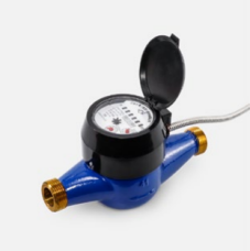
Select DAQ-GP-GWWM wireless water meter and install it at the water monitoring point. Can be powered by batteries.
Technical details:
| product | DAQ-GP-GWWM wireless water meter |
|---|---|
| measurement parameters | Accumulated traffic, accuracy level 2; Configure water meters according to the diameter of the water pipes at the monitoring points. |
| Communication parameters | Communication method: LoRa; Frequency band: 400-510MHz, 863-928MHz; Supply according to the frequency bands specified in different regions. Transmission power: 20dBm, 100mW; Receiver sensitivity: -148dBm. S485,A,B,GND; |
| Communication distance: ideal 15Km; factory environment transmission range of 300m to 5Km, with significant geographical impact. | |
|---|---|
| working voltage | 12~24VDC, Power consumption<2W. Sleep current<20 μ A. |
3.6.4 List of Traffic Monitoring Equipment
| serial number | Product Name | Equipment model and specifications | unit | quantity | Description of monitoring points |
|---|---|---|---|---|---|
| 1 | Wireless steam flow collection terminal | DAQ-GP-GWLora16AC/DAQ-GP-GWFS | platform | 1 | Collect steam flow rate |
| Wireless air flow collection terminal | DAQ-GP-GWLora16AC/DAQ-GP-GWFG | platform | Collect compressed air flow rate | ||
| Wireless water meter | DAQ-GP-GWWM162C | platform | Collect water usage |
3.7 Equipment operation status monitoring
The painting production line, as well as the equipment related to the production line, such as air compressors, refrigerators, etc., require the collection of equipment operating status, calculation and statistics of equipment operating time, analysis of equipment efficiency and operating economy.
Select the DAQ-GP-GWLoRaWAN wireless acquisition module and obtain the device's operating status through RS485, switch quantity, analog quantity and other interfaces or signal acquisition.
Technical details:
DAQ-GP-GWLoRaWAN wireless acquisition module, designed for low power consumption and battery power supply, integrates AI, DI, DO, and RS485 interfaces to collect signals from devices. In low-power mode, AI overload and DI displacement can trigger the module to upload data. DO can control the start and stop of equipment. Signals can be collected from components such as tower lights, control buttons, contactors, relays, frequency converters, transmitters, etc., and equipment operation data can also be read from equipment PLCs and control instruments through RS485 interfaces.
| product | DAQ-GP-GWLoRaWAN wireless acquisition module |
|---|---|
| Temperature and humidity parameters | Temperature range: -40~120 ℃, accuracy: ± 0.3 ℃; Humidity range: 0-100% RH accuracy: ± 3% RH. |
| Communication parameters | Communication method: LoRa; Frequency band: 400-510MHz, 863-928MHz; Supply according to the frequency bands specified in different regions. Transmission power: 20dBm, 100mW; Receiver sensitivity: -148dBm. S485,A,B,GND; Communication distance: ideal 15Km; factory environment transmission range of 300m to 5Km, with significant geographical impact. |
| 1X RS485 | Data bits: 7, 8; Stop position: 1, 2; Check bits: None, Even, Odd; Baud rate: 1200 bps~115200Kbps; |
| DI | 3-channel DI: Passive, NPN type contacts, active contacts below DC24V voltage. |
| DO | 1-channel DO, electronic contact |
| AI | Analog signal input: DC0-20mA, DC4-20mA, DC0-5V, DC0-10V, etc; Temperature Sensor: PT100, PT1000, Cu50, as well as S, J, K type thermocouples; Input isolation: 2.5KVDC; Insulation resistance: 100M Ω, 500VDC; Conversion accuracy: 0.1% F.S; Optional 4AI module. |
| power supply | Working voltage: DC6-24V; Maximum power consumption: ≤ 1W. |
| Overall dimensions | Host size: 53mm * 95mm * 95mm. Installation of guide rails. |
List of devices for collecting operational status:
| serial number | Product Name | Equipment model and specifications | unit | quantity | Description of monitoring points |
|---|---|---|---|---|---|
| 1 | Wireless acquisition module | DAQ-GP-GWLoRaWAN62A | platform | 1 | |
4. System communication network scheme design
4.1 System Communication Network Design Description
The system communication network can be simply divided into two parts: one is the communication network for obtaining data, which collects information at the device end
Number, read data, upload to the communication network of the server; The second is the platform communication network, which is the communication network for the platform to publish system data.
4.1.1 Data Acquisition Communication Network
According to the planar distribution of the collection points, set up one DAQ-GP-GWLoRaWAN IoT or one DAQ-GP-GW87 wireless communication terminal in an area with an average radius of 300 to 500 meters, so that the LoRa wireless coverage of IoT and the wireless communication terminal covers the distribution area of all monitoring points.
If data is transmitted through the internal LAN of the enterprise, deployed on servers within the enterprise, or accessed through the internal network of the enterprise
In the case of the Internet, DAQ-GP-GWLoRaWAN6 or DAQ-GP-GW87 needs to be installed in locations with enterprise LAN interfaces or areas covered by enterprise Wi Fi.
If you don't use an enterprise LAN, such as building your own communication network or uploading data to a cloud server using 4G/5G, you only need to select a convenient location to install theIoTswitch or wireless communication terminal.
4.1.2 Platform communication network
Platform communication network is a digital platform software that distributes data and alarm information to authorized computers, mobile phones, and workshop billboards.
The computers and workshop signs of the staff can access the server through LAN and the Internet, and obtain authorized viewing data from the server; Authorized mobile phone users can access the server to obtain platform data through the Internet.
4 2 IoT Description of Wireless Communication Terminals
Wireless devices such asSensorand wireless acquisition modules at monitoring points upload data through LoRa wireless communication. DAQ-GP-GWLoRaWAN or DAQ-GP-GW87 wireless communication terminal is required as the receiving end to read the data uploaded by the acquisition node devices, perform data processing, communication conversion, and communication interface conversion, and then forward the data to the factory digital platform through Ethernet, Wi Fi, or 4G/5G.
As the core of the network,IoTis a wireless communication terminal that serves as a communication hub and bridge between monitoring points and platforms. It initiates and manages the sensor network, coordinates sensor node communication, implements communication management,IoTandProtocolconversion, data processing, forwarding, and other functions, and builds a more stable, reliable, and secure intelligent sensor network.
The main difference between DAQ-GP-GWLoRaWAN and DAQ-GP-GW87 wireless communication terminals is the configuration of Hardware, both supporting Ethernet, Wi Fi, 4G/5G. DAQ-GP-GWLoRaWAN supports 2 LoRa channels, while DAQ-GP-GW87 supports 1 to 4 LoRa channels. Additionally, DAQ-GP-GW87 can be equipped with a touch screen to process, display, and alarm the collected contacts. The staff will monitor the operation status of related equipment on site Real-time.
4.3 Technical Details
IoT is a wireless communication terminal that can be configured as a multi master station and multi sub station role to read data from multiple devices in the network and forward it to multiple platforms.
Support MQTT, SOAP, Modbus, 101, 102, 103, 104, 645 and other communication Protocol; API interface; Redis data structure; DAQ-GP-GW/9-DB database format, supports writing MS SQL, My SQL, ORACLE and other databases。
Technical parameters:
| Name type | DAQ-GP-GWLoRaWAN IoT Off | DAQ-GP-GW87 wireless communication terminal |
|---|---|---|
| LoRa | Frequency band: 400-510MHz, 863-928MHz; Supply according to the frequency bands specified in different regions. | |
| Transmission power: 20dBm, 100mW; Receiver sensitivity: -148dBm. | ||
| Ideal transmission of 15Km; factory environment transmission of 300m to 5Km, greatly affected by geographical environment. | ||
| WI-FI | Frequency: 5.150-5.875 GHz. | |
| Wireless standard: 802.11 b/g/n/ac; Maximum transmission rate: 433.3M; maximum transmission power: 18dBm. | ||
| 4G/5G | LTE,UL:375Kbps/1Gbps,DL:300Kbps/200Mps. | |
| RS485 | Nothing | 3, data bits: 7, 8; Stop position: 1, 2; Check bits: None, Even, Odd; Baud rate: 1200 bps~115200Kbps; |
| Ethernet | 10/100/1000Mbps, Adaptive; Connector: RJ45. | |
| On site display | Nothing | Can be equipped with a touch screen, with optional sizes. |
| working voltage | DC24V; Maximum power consumption: ≤ 5W. | AC220V; Maximum power consumption: ≤ 30W. |
| Installation Method | Wall mounted installation or rail mounted installation. | wall-mounted installation |
| Usage environment | Fully industrial grade design, ambient temperature: -40 to+85 ℃; Environmental humidity: relative humidity of 95%. |
4.4 List of Communication Network Equipment
| serial number | Product Name | Equipment model and specifications | unit | quantity | Description of monitoring points |
|---|---|---|---|---|---|
| 1 | IoT off | DAQ-GP-GWLoRaWAN6GI2S | platform | 1 | |
| Wireless communication terminal | DAQ-GP-GW872G6IAC | set | 1 |
5. Schematic diagram of system equipment configuration
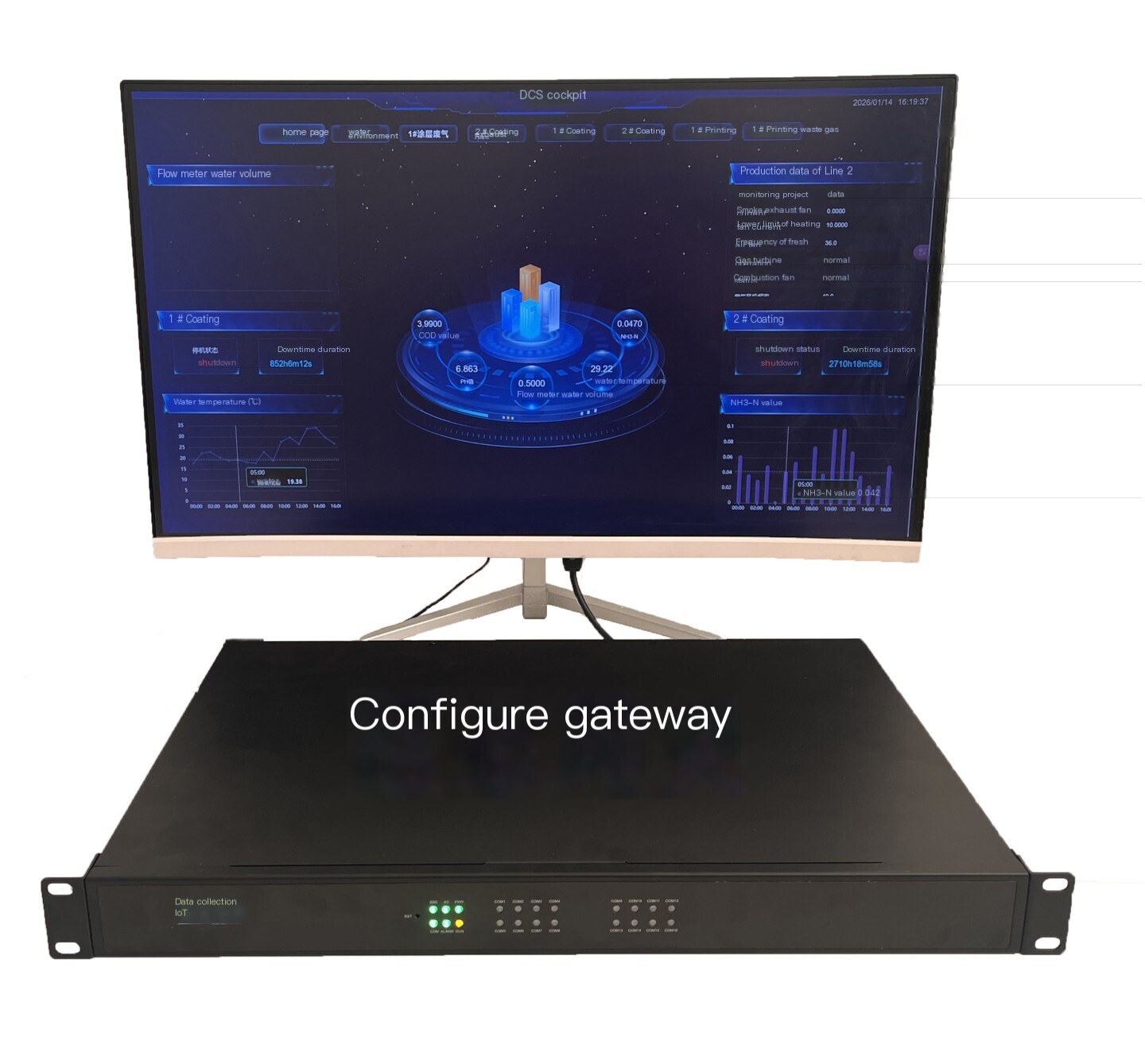
Divided into three parts, platform data release, system communication networkData Acquisition, Display system configuration and functionality.
5.1 Platform data release
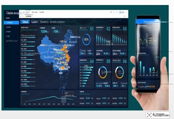
The platform publishes Real-time data, alarm information, and Data Analytics reports through the Internet and LAN (Local Area Network). Authorized accounts can access data within their permissions through computers, mobile phones, and workshop dashboards.
5.2 Network diagram of data communication layer equipment
The communication network of the data communication layer is composed of IoT and wireless communication terminals as the core. The daq iot data acquisition IoT communication network is composed of two types of networks, LAN (Local Area Network) and Internet (Internet), which jointly construct the data transmission channel between the communication layer devices and the platform layer.
5.3 Equipment layer configuration and communication diagram
The device layer consists of wireless Sensor, wireless acquisition module, wireless acquisition terminal, as well as various instruments, control modules, etc.
Monitoring points collect signals or read data from devices, and upload the data to IoT or wireless communication terminals through LoRa. The data is forwarded to the platform by Gateway and the communication terminal.
6. Introduction to Digital Platforms
6.1 Platform Configuration Plan Description
The digital platform for automotive parts painting line consists of servers and application software.
Users can choose to deploy servers and build their own digital platform; You can also choose to rent the digital cloud platform ofShanghai DAQ-IoTTechnology.
User built digital platforms have relatively high investment costs, requiring additional servers and software, as well as installation, integration, and debugging costs; In addition, maintenance of the platform is also required in the later stage, increasing the cost of operation and maintenance.
Renting the cloud platform of Shanghai DAQ-IoT technology reduces users' initial investment and later O&M costs, and [daq iot data acquisition IoT does not have the troubles of O&M.
6.2 Introduction to Digital Platform Functions
The DAQ for IIOT scada system factory digitalization platform software from TERM009TOKEN is a cloud based SCADA system factory digitalization application software that embeds intelligent analysis modules for device operation data and management modules. It can be installed onPrivate CloudorPublic Cloudservers.
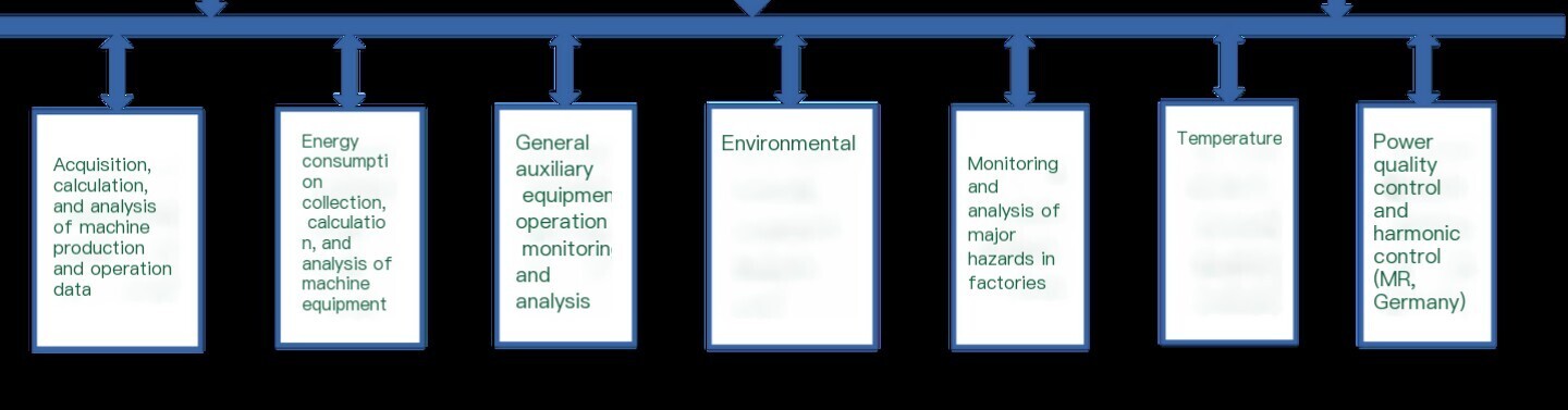
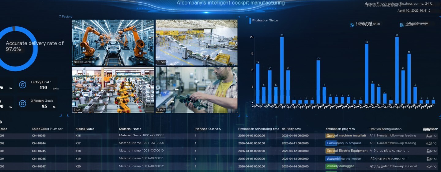
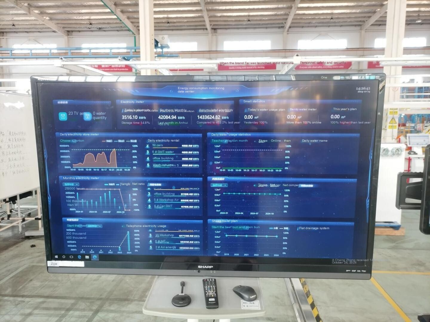
Digital platform with built-in efficient data engine, based on C/S and B/S architecture, cross platform Real-time database. Widely used for online monitoring of factory production equipment operation Data Acquisition and Real-time. Design, configure, and program according to the specific functional needs of users, to meet the differentiated requirements of different enterprises for factory digitization.
Single machine capacity exceeds 10 million points;
Read and write Real-time data peak exceeds 4 million records per second; The peak of reading and writing historical data exceeds 2 million records per second;
Support simultaneous connection of over 1000 concurrent clients.
Has powerful and easy-to-use graphics configuration; Support web publishing&mobile browsing, as well as mobile app operation browsing, displaying information such as Real-time/historical data, alarms, reports, flowcharts, etc.
Support engineer station mode, allowing for local development of projects on remote servers.
Rich communication Protocol and communication interfaces, supporting OPC, Modbus, MQTT, SOAP, API, and PLC
DCS、 More than 20 major categories and over a hundred types of communication across multiple industries such as electricity and environmental protection, as well as various intelligent devices Protocol; Supports TCP, UDP, serial port, and 4G communication methods.
Support connecting to relational databases such as MySQL, and automatically dumping data to relational databases.
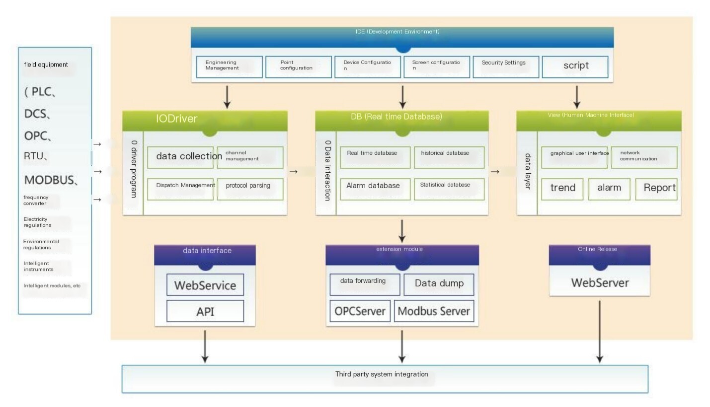
IO drive
IO driver is the data reading module of the DAQ for IIOT scada universal industrial Data Acquisition system platform, which completes communication between the platform and external devices. The IO driver reads the Real-time data from external devices and forwards control instructions issued by the DAQ for IIOT scada Universal Industrial Data Acquisition system platform to external devices.
development environment IDE
The development environment IDE is a development module for DAQ for IIOT scada general industrial Data Acquisition system integration, which completes system function configuration, such as data points, devices, screens, user management, security, and engineering encryption configuration and settings.
human-machine interface View
The human-machine interface View is the operational module of the DAQ for IIOT scada universal industrial Data Acquisition system platform, which runs and displays user developed applications, realizes platform user interaction, and provides various data display methods such as flowcharts, historical/Real-time trends, historical/Real-time alarm displays, and reports
Formula.
Real-time database DB
TheReal-timedatabase DB is the data processing core module of the DAQ for IIOT scada general industrialData Acquisitionsystem platform. It is the center of the system and completes data processing, such asReal-timedata processing, historical data storage, alarm processing, and statistical data processing; Simultaneously providing data services for other modules such as View, IO drivers, WebServer, etc.
Online Release WebServer
Web Server is a module that provides web services for users, supporting HTML5 browser access to running screens and data. It allows remote viewing of on-site data through the Internet or local area network, enabling timely understanding of the production and operation situation on site.
External communication interface
The DAQ for IIOT scada Universal Industrial Data Acquisition system platform provides rich external communication methods and exchanges data with other systems, including WebService
REST API, OPC UA Server, OPC XMLDA Server, Modbus Server, and Comm. Among them, WebService, REST API, OPC UA Server, OPC Server, and Modbus Server all use the standard public version Protocol, which does not require additional adaptation work; DAQServer is a private Protocol used for large-scale systemsHigh Concurrency、 Efficient and secure application scenarios.


评论
发表评论