Based on non-contact invasive laser ranging and wireless RFID identification technology - Automobile Factory Production Line Trolley Displacement Safety Monitoring and Early Warning System
As a professional provider of IoT data acquisition solutions and an expert in industrial IoT data acquisition, the editor of Shanghai Data Acquisition IOT Technology Co., Ltd, (daq-iot) hereby presents the following introduction, and sincerely welcomes discussions and exchanges. Supported Communication Interfaces: CAN, RS485, Mbus, 4–20mA, Profibus, CC-Link, HART, digital I/O, etc. Industrial Protocols: Modbus RTU/TCP, HJ212, IEC104, DLT645, DLMS, IEC61850, MQTT, etc. Mail:export@daq-iot.com
【Shanghai DAQ-IoTNetwork Technology Co., Ltd】
Automobile production line trolley displacement safety monitoring system

- Project Background
The production line of a certain automobile factory in Shandong adopts a conveyor belt+trolley operation mode, with 14 trolleys carrying the entire car and its components in circulation on the production line. During the production process, the trolley needs to maintain a relatively safe distance (30mm) from the entire machine. If displacement exceeds the standard, it may cause the entire machine to fall, equipment damage, and personnel safety accidents. The traditional manual monitoring method has problems such as response lag, large errors, and inability to provide early warning forReal-time. There is an urgent need for an automated and high-precision displacement monitoring system to achieve closed-loop management and control ofReal-timemonitoring, over limit warning, emergency shutdown, risk elimination, and operation recovery. - Project Requirements
passWireless laser ranging technologyReal-time monitors the relative displacement status of 14 trolleys on the production line. When the safe distance is exceeded, software prompts an alarm and physical sound and light alarms are used to cut off the conveyor belt of the production line, eliminating the risk of complete machine falling caused by trolleys exceeding the safe distance, ensuring stable operation of the production line, and improving the level of production safety control. - Solution Architecture
3.1 Hardware Deployment and Function Implementation
- Deployment of laser ranging module:
Place Wi Fi routers on site to establish a local area network, and install battery power supply at the front ends of 14 vehiclesWi Fi Laser Sensor, The monitoring range ofSensoris 0-500mm, accurately collecting the relative distance data between the vehicle and the whole machine. The collected data is transmitted to the local computer through Wi Fi intranet to ensure the stability and performance of data transmission. - Deployment of RFID Area Identification Module:
Install one RFID card reader at each end of the conveyor belt, and synchronously install RFID identification cards on the same side as the laser Sensor on each vehicle. When the vehicle enters the designated monitoring area, the RFID card readers at both ends read the identification card information and provide feedback to the upper computer with the signal "the vehicle has entered the monitoring area", and the system starts ranging monitoring; When the vehicle leaves the monitoring area, the system pauses the distance measurement of the vehicle to avoid interference from invalid data. - Safety control execution equipment:
On site installation of 1 unit485 alarm lightWhen the measured distance of any vehicle exceeds the safety threshold of 30mm, it will receive instructions from the upper computer to trigger an audible and visual alarm and promptly remind on-site employees. Install 1 unit485 relayLinked with the conveyor belt control system, it receives instructions from the upper computer to cut off the power of the conveyor belt when exceeding the standard, achieving emergency stop of the line and avoiding the expansion of risks.
(4) Upper computer software functions
Data Acquisition and Security Control:
The software receives distance data from 14 Wi Fi lasers through Wi Fi and automatically compares it with a 30mm safety threshold. When the data exceeds the threshold, immediately perform a triple operation: ① trigger the 485 alarm light sound and light alarm; ② Control the 485 relay to cut off the power supply of the conveyor belt; ③ Display the alarm car serial number and the distance value exceeding the standard in the software interface pop-up window, ensuring that on-site employees can quickly locate the problematic car.
One click control function:
One click start, click to activate the monitoring function of all online vehicles, Sensor resumes Data Acquisition, RFID card reader starts area recognition, and the system enters normal monitoring state; One click sleep mode, after clicking, the system will turn off non essential functions such as laser SensorData Acquisitionand RFID recognition. The device will switch to low-power mode to avoid prolonged standby and low battery life, ensuring normal operation of the device during the next startup and eliminating missed testing problems caused by power outages.
Visual interface display:
The software's large screen interface adopts a partition design to clearly display key information.
Vehicle status area: displays the serial numbers (1-14) of 14 vehicles, whether they are currently in the monitoring area, and the Real-time value (unit: mm) of the distance to the safety threshold;
Equipment status area: relay status, alarm light status, RFID identification card recognition status.
Alarm information area:Real-timedisplays the alarm car serial number, over limit distance, and alarm occurrence time. After the alarm is cleared, historical data is automatically recorded, and traceability query is supported.
Fault recovery and data recording:
After the on-site employees eliminate the risks, they click the "Fault Relief" button through the software interface, and the system automatically restarts the distance measurement function of the vehicle. After confirming safety, the employees can click "Resume Operation" to restore the conveyor belt to work. The software automatically records all alarm events and equipment operation status data, forming a historical ledger that supports querying and exporting based on time, vehicle serial number, and other conditions, providing data support for production management and equipment maintenance.
(5) Scheme architecture diagram
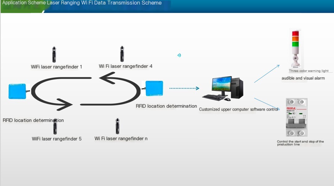
- implementation process
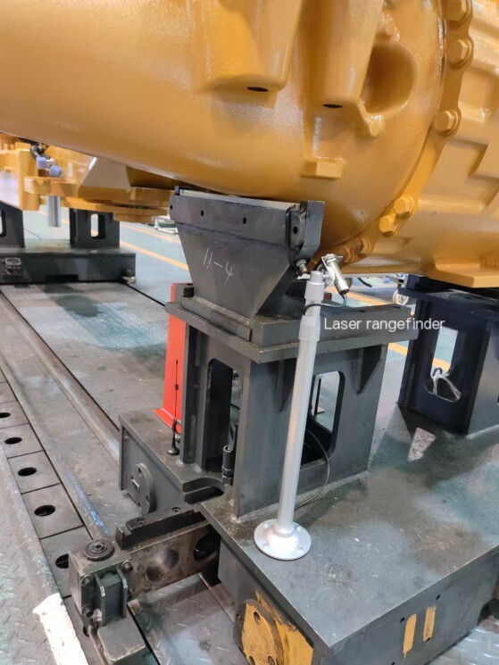
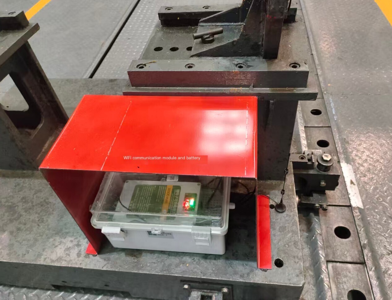
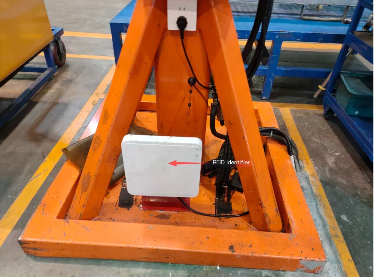
- Debugging and implementation results
On site industrial computer
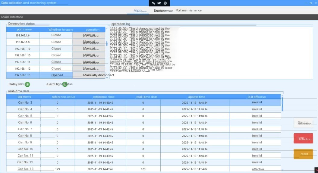
System Display Page
Device Management
Port management
Add Device
1. RFID reader (received through Lora)
Read tags:
52 46 02 00 00 80 00 13 50 11 01 0C E2 80 68 94 20 00 40 31 AF 16 C9 AD 05 01 26 0F
The yellow part is the label data (there are a total of 14 label data, arranged from top to bottom corresponding to labels 1 to 14, which correspond to 14 cars respectively)
| E280689420004031AF16E1B3 | |
| E280689420005031AF16CA03 | |
| E280689420004031AF16C9A8 | |
| E280689420004031AF16C9C4 | |
| E280689420005031AF16C96F | |
| E280689420004031AF16C9EC | |
| E280689420005031AF16C956 | |
| E280689420004031AF16E1A7 | |
| E280689420005031AF16CE54 | |
| E280689420005031AF16C8DF | |
| E280689420005031AF16C99A | |
| E280689420004031AF16C9AD | |
| E280689420005031AF16CA00 | |
| E280689420005031AF16C942 | |
2. Laser rangefinder (viaLora moduleReceived, modbus Protocol address is 3-17)
Read distance (example: label 1 corresponds to laser ranging address 03, label 2 corresponds to address 04, and so on)
Issued: 01 03 02 01 00 01 D4 72
Received: 01 03 02 01 F0 B9 90
The integer reading is 496 (0x01F0) in millimeters.
Read instructions for addresses 03 to 17:
03 03 02 01 00 01 35 B1 Read register 513 at address 03
04 04 03 02 00 01 85 B1 reads register 513 of address 04
05 05 03 02 01 00 01 D4 72 Read register 513 at address 05
06 06 03 02 01 00 01 24 73 Read register 513 at address 06
07 07 03 02 01 00 01 75 B3 reads register 513 at address 07
08 08 03 02 00 01 C5 B3 reads register 513 of address 08
09 09 03 02 01 00 01 14 70 Read register 513 at address 09
10 (0A) 0A 03 02 01 00 01 E4 73 Read register 513 at address 10
11 (0B) 0B 03 02 01 00 01 B5 B2 reads register 513 of address 11
12 (0C) 0C 03 02 01 00 01 45 B2 Read register 513 of address 12
13 (0D) 0D 03 02 01 00 01 14 71 Read register 513 at address 13
14 (0E) 0E 03 02 01 00 01 E4 72 Read register 513 of address 14
15 (0F) 0F 03 02 01 00 01 B5 B3 Read register 513 at address 15
16 (10) 10 03 02 01 00 01 05 B0 Read register 513 at address 16
17 (11) 11 03 02 01 00 01 54 71 Read register 513 at address 17
3. Relay (wired 485 direct connection to computer, modbus Protocol address is 2, function: control the start and stop of the production line)
Read relay status: (optional, check if it is necessary to check the relay status before issuing control)
Example sent: 02 02 00 00 02 F9 F8
Return: 02 02 01 00 A1 CC
Analysis: The fourth byte 00 is off and 01 is on
Control on/off:
Control interruption: 02 05 00 00 FF 00 8C 09 □
Return: 02 05 00 FF 00 8C 09
Control Pass: 02 05 00 00 00 CD F9 □
Return: 02 05 00 00 00 CD F9
Byte 3, 4: Register Address
Byte 5, 6, FF 00 is off, 00 00 00 is on
4. Alarm light (wired 485 connection to computer, modbus Protocol address is 1)
Trigger alarm: turn on the red light and turn on the buzzer
01 05 00 FF 00 8C 3A is in the open red state;
01 05 00 00 00 CD CA is in the closed red state;
Buzzer on: 01 05 00 18 FF 00 0C 3D;
Buzzer off: 01 05 00 18 00 00 4D CD.
There are two readers/writers in this project, fixed at both ends of the production line. 14 label cards and 14 laser rangefinders+14 Lora modules are located on the 14 trolleys of the production line. When the trolley passes by the first reader/writer, it will actively send a label data to the reader/writer, marking the first time the trolley passes. At this time, distance measurement is carried out (assuming the label data is number 1, then issue the 03 address command to read the laser rangefinder value). Based on the distance X0 measured by the first reader/writer on the trolley, if the relative distance (Xn-X0) is ≤ 30mm, the alarm light will be triggered and the production line will stop running (the control relay will be disconnected). When the same label is recognized passing through the second reader/writer, this process is completed. If an alarm occurs during operation, the on-site personnel must eliminate the risk and manually restore it on the upper computer (control the relay to turn on). After restoration, the above process can continue.
The upper computer software must display distance information, relay status, control relay on/off buttons, and alarm reasons (such as the alarm information generated by the number of cars)


评论
发表评论