Box Transformer Intelligent Measurement and Control Device (Terminal)
As a professional provider of IoT data acquisition solutions and an expert in industrial IoT data acquisition, the editor of Shanghai Data Acquisition IOT Technology Co., Ltd, (daq-iot) hereby presents the following introduction, and sincerely welcomes discussions and exchanges. Supported Communication Interfaces: CAN, RS485, Mbus, 4–20mA, Profibus, CC-Link, HART, digital I/O, etc. Industrial Protocols: Modbus RTU/TCP, HJ212, IEC104, DLT645, DLMS, IEC61850, MQTT, etc. Mail:export@daq-iot.com
1 Product Overview
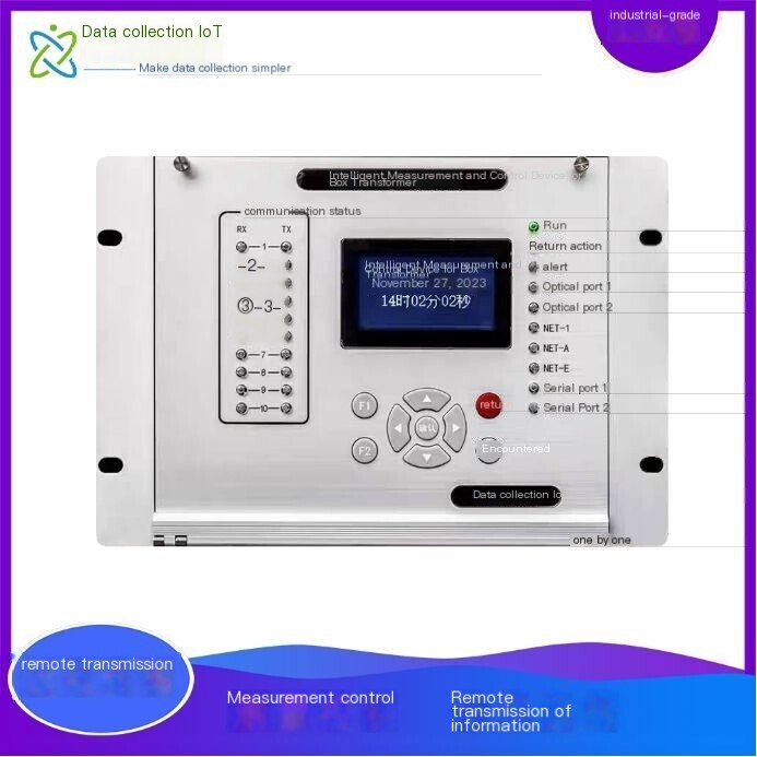
SC-GP-MDC It is a box type intelligent measurement and control device/terminal launched byShanghai DAQ-IoTTechnology, suitable forPVorWind power booster stationTo provide comprehensive protection, measurement, control, adjustment, and remote information transmission functions for the integration of new energy generation into the grid. Implement the "unmanned and few person on duty" operation management mode for wind power orPVprojects.
The device adopts the latest technology32-bit high-performance processorPlatform design, combined with the company's mature and stable software algorithms, ensures product stability and reliability, making the product easier to use and more functional.
2 Service Philosophy
Our company solemnly promises:
You are not only purchasing products, but also providing meticulous and thoughtful technical support services!!!( =^_^= )
This product only requires ordinary workers to connect and install it on site! No debugging required!
We provide free remote guidance, remote configuration and debugging services, and send data to the user's designated cloud platform.
Free consultation service forIoTsolution!
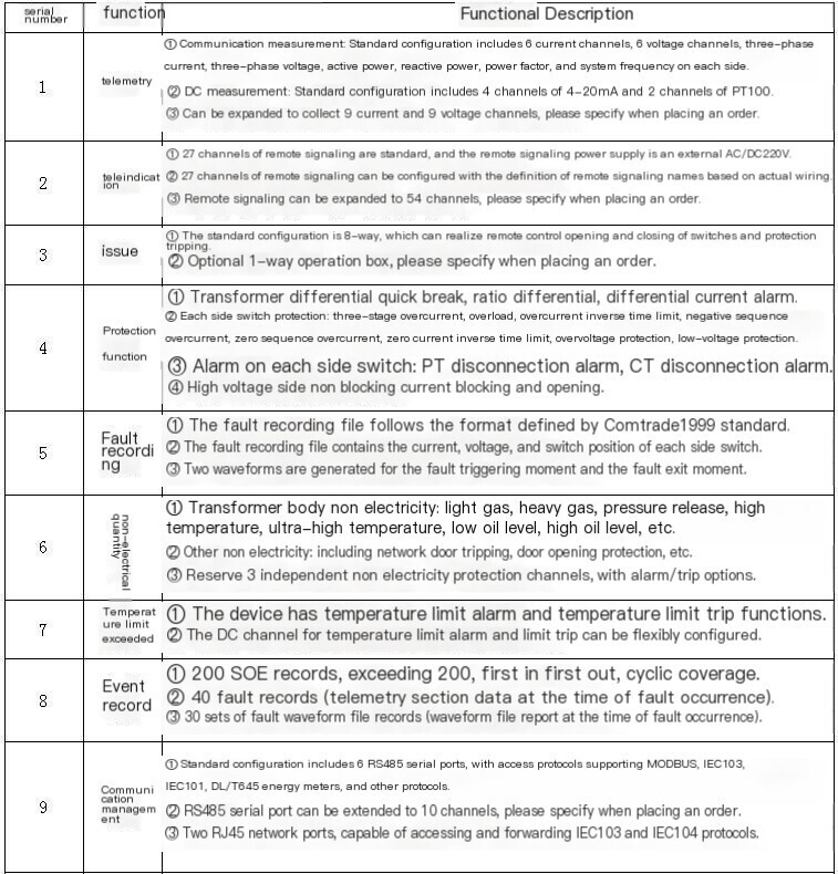
3 Function Configuration

4 Electrical Characteristics
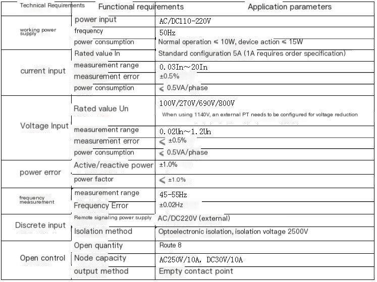
4.1Communication characteristics
l RS485 serial port Baud rate 1200bps~9600bps
L optical port ST interfaceSingle mode dual core ≥ 20km
l RJ45 Ethernet port 10M/100M adaptive
5 structural characteristics
The device adopts a rear plug-in structure with a closed shell; The chassis adopts embedded installation method and is wired behind the box.
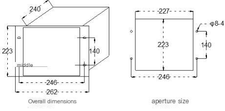
Dimensions of the device: 223 × 262 × 240mm (height × width × depth);
Installation hole size: 223 × 227mm (height × width);
Installation fixed hole spacing: 140 × 246mm (height × width), installation hole: 4 × Φ 8mm.
The device design adopts a modular design concept, where different configuration requirements are combined and configured by various functional components as needed, achieving standardization of functional modules. The device consists of an analog input AI plugin, a main control MAIN plugin, a basic remote signaling DI plugin, a power/output POW plugin, a communication TX plugin, and a human-machine interface MMI component on the panel.
From right to left on the back of the chassis (as shown in Figure 3.2-1), they are: analog input AI plugin (A), main control MAIN plugin (B), basic remote signaling DI plugin (C), extended remote signaling DI plugin (D), power/output POW plugin (E), and communication TX plugin (F). The standard configuration of the device includes (A), (B), (C), (E), and (F), with 5 plugins that can meet the needs of telemetry and remote signal acquisition, output control, communication management, and ring network. If users need to add special switch signal acquisition, they can expand it by extending the remote signal DI plugin (D).
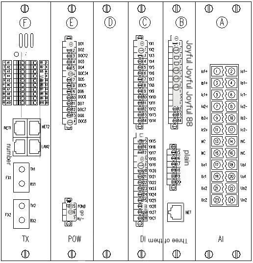
Figure 3.2-1
5.1.1 Analog inputAIPlugin(A)
The AI plugin for analog input comes standard with 6-channel current and 6-channel voltage acquisition, which can collect analog signals such as three-phase AC current and three-phase AC voltage. After the AC current and AC voltage are isolated and converted into small signals through internal transformers, they are sent to the main control MAIN plugin for signal conditioning and analog signal acquisition and calculation.
5.1.2 Main control plugin(B)
The main control MAIN plugin is the core plugin of this device, which includes analog signal conditioning, acquisition, AD conversion, protection discrimination, switch quantity acquisition, parameter and historical record storage, Real-time hard clock, etc.
The internal main control MAIN plugin and communication TX plugin of the device are directly interconnected through an internal serial port for data exchange and command execution.
5.1.3 teleindicationDI plugin(C)
The device comes standard with one basic remote signaling plugin (C). When the basic remote signaling plugin cannot meet the configuration requirements, the input capacity can be expanded by extending the remote signaling plugin (D). The basic remote signaling plugin and the extended remote signaling plugin have the same Hardware, which needs to be selected through the JP1 jumper on the remote signaling plugin. Short circuit of pins 1-2 of JP1 jumper: for basic remote signaling plug-in (C); Short circuit of pins 2-3 of JP1 jumper: for expanding the remote signaling plug-in (D).
5.1.4 Power supply/POW plug-in(E)
The power/output plug-in adopts a wide input range AC/DC dual-purpose switch power supply, with AC/DC85-265V input and DC5V output, for use in digital and analog circuits of the device.
The opening section provides 8 open contacts to achieve remote control tripping/closing control of switches, protection tripping control, and other outputs.
The power/output plug-in can be optionally equipped with a 1-way operation box, which needs to be specified by the user when ordering.
5.1.5 Communication TXPlugin(F)
The communication TX plugin is configured with communication management machine function and ring network switch function.
The communication management machine is equipped with RS485 serial port and RJ45 network port, which can receive and forward multiple protocols Protocol in the power system.
The communication TX plugin also embeds a ring network switch, which can achieve fiber self-healing ring network. The ring network switch is configured with 2 electrical ports and 2 optical ports, supporting multiple devices to network through the network.
Special note: In order to simplify the external network cable when connecting the communication management machine to the ring network switch, there is a network interface directly connected between the communication management machine and the ring network switch inside the device. When the communication management machine does not need to be directly connected to the ring network switch, all four hop blocks at JP1 position on the communication TX plugin need to be opened to avoid device IP address conflicts and affect network communication.
The default IP address for the communication TX plugin network port is as follows:
(1) The default IP address for NET1 is 192.168.1.166.
(2) The default IP address for NET2 is 192.168.3.166.
(3) The default IP address for the network port directly connected to the internal management machine and switch of the device is 192.168.2.166.
5.1.6 Human-MachineInterface components
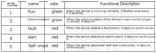
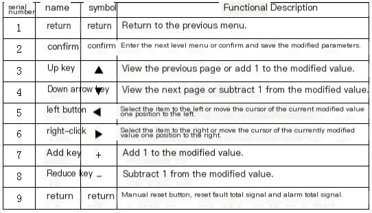
The human-machine interface component provides a wide temperature operationOLED screenConfigure 9 operation buttons to achieve human-computer interaction operation. The device panel is equipped with 5 software indicator lights and 26 Hardware driver indicator lights.
5.1.7 Indicator lights and buttons
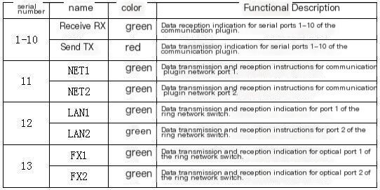
5.1.8 Hardwareindicator light
5.1.9 softwareindicator light
5.1.10Operation buttons
6 workenvironment
A place with no explosion hazard, no conductive dust, and no corrosiveness.
Environmental temperature: -40 ℃~+75 ℃
Environmental humidity: The relative humidity should not exceed 50% when the maximum temperature is 75 ℃; When the ambient temperature is 20 ℃, the maximum humidity in the environment can reach 90%
Atmospheric pressure: 80kPa~110kPa
Protection level: IP50
7 Product Features
(1) The device adopts a wide operating temperature device design, a wide temperature range OLED display screen, strong interference design, and is suitable for harsh on-site environments.
(2) All integrated circuits of the device use industrial grade components to ensure high stability and reliability of the device.
(3) Adopting a 32-bit high-performance embedded microcomputer processor, equipped with large capacity RAM and FLASH, it has strong data operation, logic processing, and information storage capabilities, fast running speed, and high reliability.
(4) Complete historical event records, fault moment section data storage, fault waveform file storage, power failure self preservation, facilitating accident analysis.
(5) The design includes RS485 serial communication, RJ45 Ethernet communication, and fiber optic communication, which can be connected to other device protocols on site to achieve data forwarding.
8 human-machine interface
The device adopts a wide temperature OLED screen, which allows users to easily browse data information, modify set parameters, and conduct transmission experiments. The device also provides detailed fault event records and fault waveform reports, helping users to promptly and accurately handle power grid accidents.
8.1 liquid crystaldisplay structure
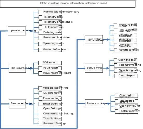
Note: The default password for the device is "1000" when it leaves the factory, and it is set for factory debugging. A super password is required.
8.2 Main menu interface
The main menu interface of the device is a multi-level structured menu. It can be selected through the directional keys, with a background color indicating that the item has been selected. After selection, press the "confirm" button to enter the next level menu.
8.3 Parameter modification process
In the main menu interface, entering any menu of parameter settings, fixed value management, debugging mode, or factory settings requires password verification before setting. Incorrect passwords cannot be set. The parameter modification process is shown in the following figure:
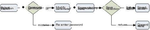
Taking the main menu ->parameter settings ->variable ratio wiring as an example, use the up and down keys to select the item to be modified, as shown in Figure 4.3-1. After selecting the item to be modified, press the "Confirm" button to enter the parameter editing mode. Reverse select the numbers with background color to edit and modify, as shown in Figure 4.3-2. Modify the size of the numerical value by pressing the up and down keys, select the digit to be modified by pressing the left and right keys, and press the "confirm" key to temporarily save the modification after completion.
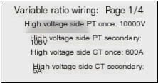
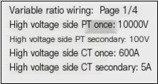
Figure 4.3-1 Figure 4.3-2
Repeat the above operation until the parameter entries that need to be modified are completed. Press the "Return" button. If the parameters have been modified, enter the "Save" interface, as shown in Figure 4.3-3. Follow the prompts and press the "Confirm" button to save. If the save is successful, a prompt will appear saying "Save successfully", as shown in Figure 4.3-4.
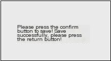
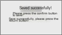
Figure 4.3-3 Figure 4.3-4
8.4 Dynamic pop-up interface
Under the data display and report display interface, a dynamic interface with fault information can automatically pop up. Press the "Return" key to exit the dynamic pop-up interface. History records can be viewed on the report display interface.
8.5 Screen saver function
To extend the service life of the LCD screen, when there is no button operation for more than 5 minutes, the screen will enter the screen protection state and the LCD screen will display black. In the screen saver state, press any button to light up the LCD screen.
9 Appendix
9.1 Electromagnetic compatibility standards
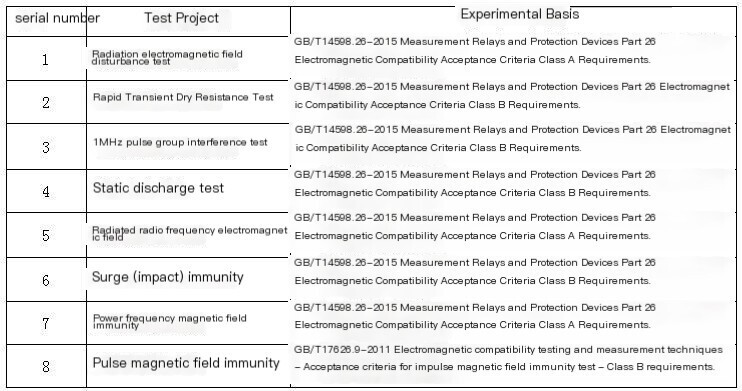
9.2 Mechanical performance standards
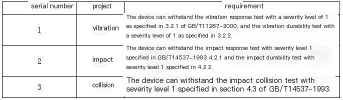
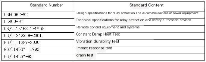
9.3 Implementation Standards


评论
发表评论