DH200 Smart Mining Aluminum Belt Scale Data AcquisitionRemote MonitoringWiring Installation Plan Control Instrument Energy Consumption
As a professional provider of IoT data acquisition solutions and an expert in industrial IoT data acquisition, the editor of Shanghai Data Acquisition IOT Technology Co., Ltd, (daq-iot) hereby presents the following introduction, and sincerely welcomes discussions and exchanges. Supported Communication Interfaces: CAN, RS485, Mbus, 4–20mA, Profibus, CC-Link, HART, digital I/O, etc. Industrial Protocols: Modbus RTU/TCP, HJ212, IEC104, DLT645, DLMS, IEC61850, MQTT, etc. Mail:export@daq-iot.com
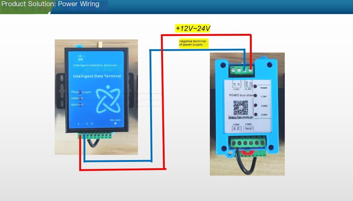

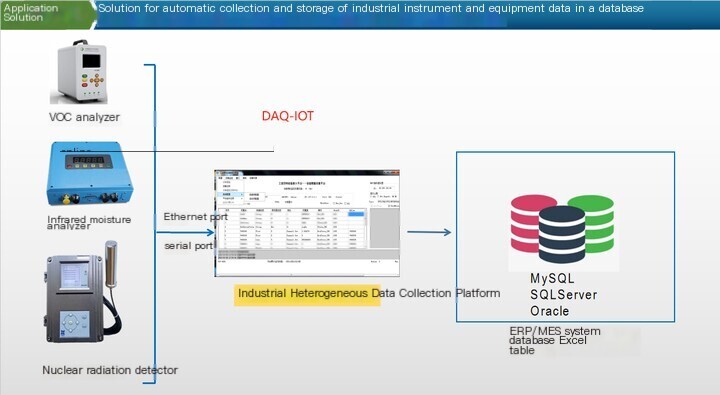
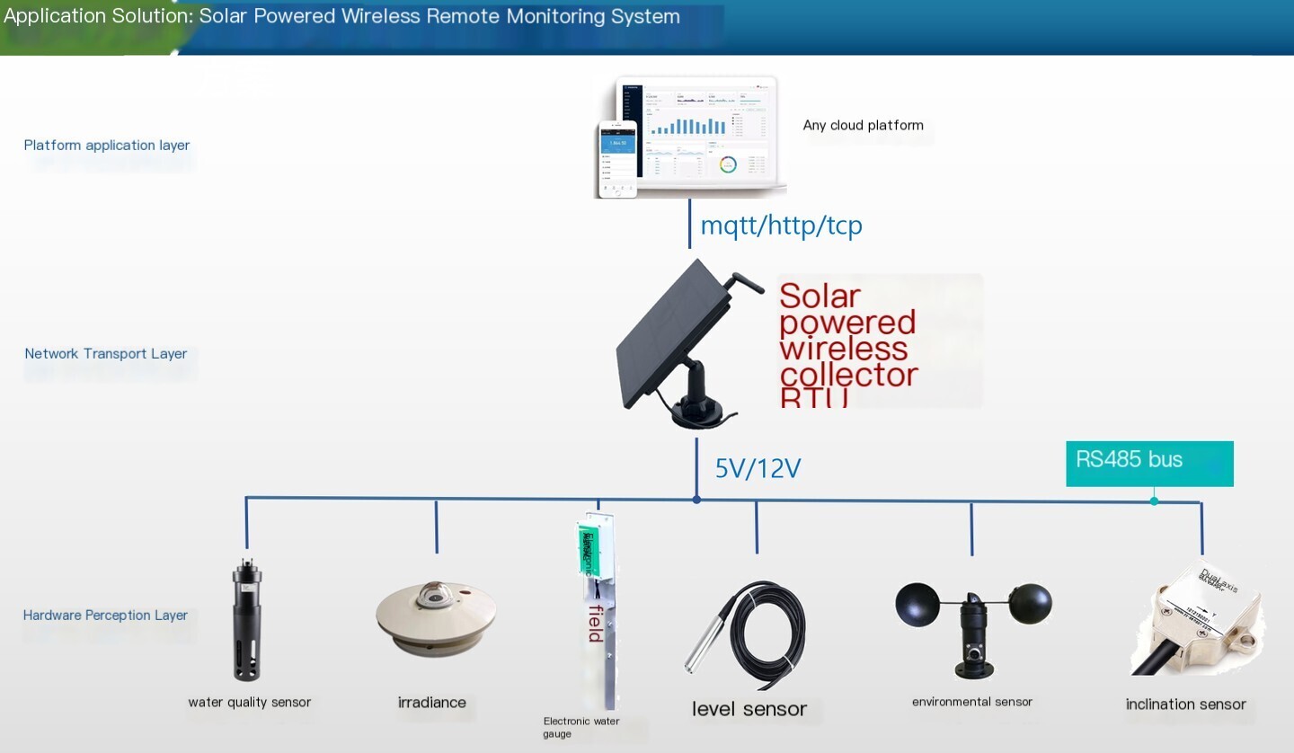
Implementation of the planbelt weigherData Acquisition, 4G wireless transmission to remote management platform, does not affect local accessDCS systemCollect data.
Connect the com1485 line on the VCC side to the belt scale 485 line, connect a to a, and connect b to b,
The customer originally connected the 485 line of the system to COM3, A to A, and B to B
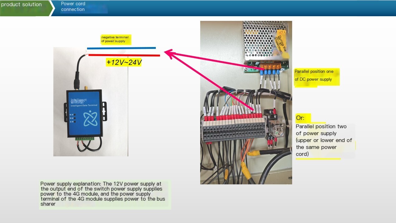
Power supply: This positive+negative power supply and the equipment above require power supply. The yellow thread is the antenna interface
Belt scale control instrument is a high-performance control instrument specifically designed for belt scales. It adopts anti-interference measures and multiple latest research results of single-chip microcontrollers, and has the characteristics of powerful functions, small size, high reliability, and strong adaptability. Suitable for controlling various forms and ranges of belt scales, used for controlling various forms of dynamic scales such as cutter scales, disc scales, and rotor scales. This instrument is suitable for the following control systems:
1. Quantitative feeder
By controlling the belt speed of the feeder or pre feeding to control the flow rate.
2. Belt scale
By controlling the belt speed to regulate the belt load, the flow rate can be controlled.
1.2 Functional Features
1. StandardRS-232Communication function with RS-485, following standardsMODBUSProtocolFast communication speed and high reliability. (Optional feature)
2. Adopt LCD display.
3. The input and output interfaces adopt various Hardware anti-interference technologies.
4. The instrument can be operated through the keyboard, external signals (ports), and upper computer.
5. IntelligencePID regulationAnd the control cycle can be set arbitrarily.
6. It can be connected to the upper computer through instrument interfaces and communication interfacesPLCOr DCS connection.
7. It has two control methods: flow control and quantitative control.
8. It has two working modes: speed regulation and constant speed.
9. It is equipped with cumulative pulse output, and the width and equivalent of each pulse (the amount of material represented by each pulse) can be set through parameters.
10. The "flow setting mode" and "start mode" of the instrument can be switched through corresponding DI input signals. When the DI is valid, it is the "external interface" mode, otherwise it is the "instrument keyboard" or "communication" mode.
11. Key parameter settings are password protected to prevent misuse by non professionals.
12. Quick parameter backup and recovery function. All internal parameters of the instrument can be backed up and restored when there are problems with the instrument parameters.
13. It has a volumetric working mode. When there is a problem with the load Sensor, the instrument can switch to volumetric working mode.
1.3 Technical parameters
1. Working power supply: 85-265VAC/10W.
2. Working environment: -10-50 ℃/5-90% RH (no condensation).
3. External dimensions: 144 (H) * 100 (0W) * 170 (D) Opening dimensions: 137 (H) * 93 (W) (unit: mm).
4. Weight detection: The resolution is 16 bits, the input sensitivity is 0.4-1.0 μ V/D (according to the factory set gain), and the error is less than 0.01%.
5. Speed measurement: The error is less than 0.01%, and the pulse frequency range is 1-3000Hz. The instrument provides a speed measurement Sensor with a working power supply of DC 15V/50mA.
6. Instrument comprehensive error: less than 0.02%.
Display digits: 5 digits (excluding cumulative values).
1.4 front panel
Button Instructions:
<table data-draft-node="block" data-draft-type="table" data-size="normal" data-row-style="normal">“ Run/Stop "toggle key (keyboard startup mode). Press this button to start the instrument in the shutdown state, and press this button to stop the machine in the startup state. Single button press. The "Initial Settings" function key. Used for initial setup and for instrument adjustment. A password is required to access this feature. Single button press. Function key for "common parameter modification". Used to modify commonly used parameters, such as traffic. Single button press. The "Auxiliary Functions" button is used for interface testing, calibration, and other functions. To access this feature, the same password is required as to enter 'Initial Settings'. Single button press. When selecting functions, use the flip button; When making numerical modifications, use the add key. Supports two types of operations: tapping and continuous pressing, with a tapping time of less than 0.3 seconds to complete one operation. When it exceeds 1 second, continue the operation. When selecting functions, use the flip button; When making numerical changes, use the decrease key. Supports two types of operations: tapping and continuous pressing, with a tapping time of less than 0.3 seconds to complete one operation. When it exceeds 1 second, continue the operation. Manual/automatic switch button. Single button press. Shift key. Select the corresponding parameters through this key in the interface testing and range calibration functions. Confirm key. Used to select and accept input results. Single button press. Cancel the input of data when using the cancel key, and cancel the operation when using related functions. Switching between numeric keypad and auxiliary display.
| Run/Stop "toggle key (keyboard startup mode). Press this button to start the instrument in the shutdown state, and press this button to stop the machine in the startup state. Single button press. | |
| The "Initial Settings" function key. Used for initial setup and for instrument adjustment. A password is required to access this feature. Single button press. | |
| Function key for "common parameter modification". Used to modify commonly used parameters, such as traffic. Single button press. | |
| The "Auxiliary Functions" button is used for interface testing, calibration, and other functions. To access this feature, the same password is required as to enter 'Initial Settings'. Single button press. | |
| When selecting functions, use the flip button; When making numerical modifications, use the add key. Supports two types of operations: tapping and continuous pressing, with a tapping time of less than 0.3 seconds to complete one operation. When it exceeds 1 second, continue the operation. | |
| When selecting functions, use the flip button; When making numerical changes, use the decrease key. Supports two types of operations: tapping and continuous pressing, with a tapping time of less than 0.3 seconds to complete one operation. When it exceeds 1 second, continue the operation. | |
| Manual/automatic switch button. Single button press. | |
| Shift key. Select the corresponding parameters through this key in the interface testing and range calibration functions. | |
| Confirm key. Used to select and accept input results. Single button press. | |
| Cancel the input of data when using the cancel key, and cancel the operation when using related functions. | |
| Switching between numeric keypad and auxiliary display. |
<table data-draft-node="block" data-draft-type="table" data-size="normal" data-row-style="normal">“ Run/Stop "toggle key (keyboard startup mode). Press this button to start the instrument in the shutdown state, and press this button to stop the machine in the startup state. Single button press. The "Initial Settings" function key. Used for initial setup and for instrument adjustment. A password is required to access this feature. Single button press. Function key for "common parameter modification". Used to modify commonly used parameters, such as traffic. Single button press. The "Auxiliary Functions" button is used for interface testing, calibration, and other functions. To access this feature, the same password is required as to enter 'Initial Settings'. Single button press. When selecting functions, use the flip button; When making numerical modifications, use the add key. Supports two types of operations: tapping and continuous pressing, with a tapping time of less than 0.3 seconds to complete one operation. When it exceeds 1 second, continue the operation. When selecting functions, use the flip button; When making numerical changes, use the decrease key. Supports two types of operations: tapping and continuous pressing, with a tapping time of less than 0.3 seconds to complete one operation. When it exceeds 1 second, continue the operation. Manual/automatic switch button. Single button press. Shift key. Select the corresponding parameters through this key in the interface testing and range calibration functions. Confirm key. Used to select and accept input results. Single button press. Cancel the input of data when using the cancel key, and cancel the operation when using related functions. Switching between numeric keypad and auxiliary display.
| Run/Stop "toggle key (keyboard startup mode). Press this button to start the instrument in the shutdown state, and press this button to stop the machine in the startup state. Single button press. | |
| The "Initial Settings" function key. Used for initial setup and for instrument adjustment. A password is required to access this feature. Single button press. | |
| Function key for "common parameter modification". Used to modify commonly used parameters, such as traffic. Single button press. | |
| The "Auxiliary Functions" button is used for interface testing, calibration, and other functions. To access this feature, the same password is required as to enter 'Initial Settings'. Single button press. | |
| When selecting functions, use the flip button; When making numerical modifications, use the add key. Supports two types of operations: tapping and continuous pressing, with a tapping time of less than 0.3 seconds to complete one operation. When it exceeds 1 second, continue the operation. | |
| When selecting functions, use the flip button; When making numerical changes, use the decrease key. Supports two types of operations: tapping and continuous pressing, with a tapping time of less than 0.3 seconds to complete one operation. When it exceeds 1 second, continue the operation. | |
| Manual/automatic switch button. Single button press. | |
| Shift key. Select the corresponding parameters through this key in the interface testing and range calibration functions. | |
| Confirm key. Used to select and accept input results. Single button press. | |
| Cancel the input of data when using the cancel key, and cancel the operation when using related functions. | |
| Switching between numeric keypad and auxiliary display. |
<table data-draft-node="block" data-draft-type="table" data-size="normal" data-row-style="normal">“ Run/Stop "toggle key (keyboard startup mode). Press this button to start the instrument in the shutdown state, and press this button to stop the machine in the startup state. Single button press. The "Initial Settings" function key. Used for initial setup and for instrument adjustment. A password is required to access this feature. Single button press. Function key for "common parameter modification". Used to modify commonly used parameters, such as traffic. Single button press. The "Auxiliary Functions" button is used for interface testing, calibration, and other functions. To access this feature, the same password is required as to enter 'Initial Settings'. Single button press. When selecting functions, use the flip button; When making numerical modifications, use the add key. Supports two types of operations: tapping and continuous pressing, with a tapping time of less than 0.3 seconds to complete one operation. When it exceeds 1 second, continue the operation. When selecting functions, use the flip button; When making numerical changes, use the decrease key. Supports two types of operations: tapping and continuous pressing, with a tapping time of less than 0.3 seconds to complete one operation. When it exceeds 1 second, continue the operation. Manual/automatic switch button. Single button press. Shift key. Select the corresponding parameters through this key in the interface testing and range calibration functions. Confirm key. Used to select and accept input results. Single button press. Cancel the input of data when using the cancel key, and cancel the operation when using related functions. Switching between numeric keypad and auxiliary display.
| Run/Stop "toggle key (keyboard startup mode). Press this button to start the instrument in the shutdown state, and press this button to stop the machine in the startup state. Single button press. | |
| The "Initial Settings" function key. Used for initial setup and for instrument adjustment. A password is required to access this feature. Single button press. | |
| Function key for "common parameter modification". Used to modify commonly used parameters, such as traffic. Single button press. | |
| The "Auxiliary Functions" button is used for interface testing, calibration, and other functions. To access this feature, the same password is required as to enter 'Initial Settings'. Single button press. | |
| When selecting functions, use the flip button; When making numerical modifications, use the add key. Supports two types of operations: tapping and continuous pressing, with a tapping time of less than 0.3 seconds to complete one operation. When it exceeds 1 second, continue the operation. | |
| When selecting functions, use the flip button; When making numerical changes, use the decrease key. Supports two types of operations: tapping and continuous pressing, with a tapping time of less than 0.3 seconds to complete one operation. When it exceeds 1 second, continue the operation. | |
| Manual/automatic switch button. Single button press. | |
| Shift key. Select the corresponding parameters through this key in the interface testing and range calibration functions. | |
| Confirm key. Used to select and accept input results. Single button press. | |
| Cancel the input of data when using the cancel key, and cancel the operation when using related functions. | |
| Switching between numeric keypad and auxiliary display. |
<table data-draft-node="block" data-draft-type="table" data-size="normal" data-row-style="normal">“ Run/Stop "toggle key (keyboard startup mode). Press this button to start the instrument in the shutdown state, and press this button to stop the machine in the startup state. Single button press. The "Initial Settings" function key. Used for initial setup and for instrument adjustment. A password is required to access this feature. Single button press. Function key for "common parameter modification". Used to modify commonly used parameters, such as traffic. Single button press. The "Auxiliary Functions" button is used for interface testing, calibration, and other functions. To access this feature, the same password is required as to enter 'Initial Settings'. Single button press. When selecting functions, use the flip button; When making numerical modifications, use the add key. Supports two types of operations: tapping and continuous pressing, with a tapping time of less than 0.3 seconds to complete one operation. When it exceeds 1 second, continue the operation. When selecting functions, use the flip button; When making numerical changes, use the decrease key. Supports two types of operations: tapping and continuous pressing, with a tapping time of less than 0.3 seconds to complete one operation. When it exceeds 1 second, continue the operation. Manual/automatic switch button. Single button press. Shift key. Select the corresponding parameters through this key in the interface testing and range calibration functions. Confirm key. Used to select and accept input results. Single button press. Cancel the input of data when using the cancel key, and cancel the operation when using related functions. Switching between numeric keypad and auxiliary display.
| Run/Stop "toggle key (keyboard startup mode). Press this button to start the instrument in the shutdown state, and press this button to stop the machine in the startup state. Single button press. | |
| The "Initial Settings" function key. Used for initial setup and for instrument adjustment. A password is required to access this feature. Single button press. | |
| Function key for "common parameter modification". Used to modify commonly used parameters, such as traffic. Single button press. | |
| The "Auxiliary Functions" button is used for interface testing, calibration, and other functions. To access this feature, the same password is required as to enter 'Initial Settings'. Single button press. | |
| When selecting functions, use the flip button; When making numerical modifications, use the add key. Supports two types of operations: tapping and continuous pressing, with a tapping time of less than 0.3 seconds to complete one operation. When it exceeds 1 second, continue the operation. | |
| When selecting functions, use the flip button; When making numerical changes, use the decrease key. Supports two types of operations: tapping and continuous pressing, with a tapping time of less than 0.3 seconds to complete one operation. When it exceeds 1 second, continue the operation. | |
| Manual/automatic switch button. Single button press. | |
| Shift key. Select the corresponding parameters through this key in the interface testing and range calibration functions. | |
| Confirm key. Used to select and accept input results. Single button press. | |
| Cancel the input of data when using the cancel key, and cancel the operation when using related functions. | |
| Switching between numeric keypad and auxiliary display. |
| Run/Stop "toggle key (keyboard startup mode). Press this button to start the instrument in the shutdown state, and press this button to stop the machine in the startup state. Single button press. | |
| The "Initial Settings" function key. Used for initial setup and for instrument adjustment. A password is required to access this feature. Single button press. | |
| Function key for "common parameter modification". Used to modify commonly used parameters, such as traffic. Single button press. | |
| The "Auxiliary Functions" button is used for interface testing, calibration, and other functions. To access this feature, the same password is required as to enter 'Initial Settings'. Single button press. | |
| When selecting functions, use the flip button; When making numerical modifications, use the add key. Supports two types of operations: tapping and continuous pressing, with a tapping time of less than 0.3 seconds to complete one operation. When it exceeds 1 second, continue the operation. | |
| When selecting functions, use the flip button; When making numerical changes, use the decrease key. Supports two types of operations: tapping and continuous pressing, with a tapping time of less than 0.3 seconds to complete one operation. When it exceeds 1 second, continue the operation. | |
| Manual/automatic switch button. Single button press. | |
| Shift key. Select the corresponding parameters through this key in the interface testing and range calibration functions. | |
| Confirm key. Used to select and accept input results. Single button press. | |
| Cancel the input of data when using the cancel key, and cancel the operation when using related functions. | |
| Switching between numeric keypad and auxiliary display. |
| Run/Stop "toggle key (keyboard startup mode). Press this button to start the instrument in the shutdown state, and press this button to stop the machine in the startup state. Single button press. | |
| The "Initial Settings" function key. Used for initial setup and for instrument adjustment. A password is required to access this feature. Single button press. | |
| Function key for "common parameter modification". Used to modify commonly used parameters, such as traffic. Single button press. | |
| The "Auxiliary Functions" button is used for interface testing, calibration, and other functions. To access this feature, the same password is required as to enter 'Initial Settings'. Single button press. | |
| When selecting functions, use the flip button; When making numerical modifications, use the add key. Supports two types of operations: tapping and continuous pressing, with a tapping time of less than 0.3 seconds to complete one operation. When it exceeds 1 second, continue the operation. | |
| When selecting functions, use the flip button; When making numerical changes, use the decrease key. Supports two types of operations: tapping and continuous pressing, with a tapping time of less than 0.3 seconds to complete one operation. When it exceeds 1 second, continue the operation. | |
| Manual/automatic switch button. Single button press. | |
| Shift key. Select the corresponding parameters through this key in the interface testing and range calibration functions. | |
| Confirm key. Used to select and accept input results. Single button press. | |
| Cancel the input of data when using the cancel key, and cancel the operation when using related functions. | |
| Switching between numeric keypad and auxiliary display. |
| Run/Stop "toggle key (keyboard startup mode). Press this button to start the instrument in the shutdown state, and press this button to stop the machine in the startup state. Single button press. | |
| The "Initial Settings" function key. Used for initial setup and for instrument adjustment. A password is required to access this feature. Single button press. | |
| Function key for "common parameter modification". Used to modify commonly used parameters, such as traffic. Single button press. | |
| The "Auxiliary Functions" button is used for interface testing, calibration, and other functions. To access this feature, the same password is required as to enter 'Initial Settings'. Single button press. | |
| When selecting functions, use the flip button; When making numerical modifications, use the add key. Supports two types of operations: tapping and continuous pressing, with a tapping time of less than 0.3 seconds to complete one operation. When it exceeds 1 second, continue the operation. | |
| When selecting functions, use the flip button; When making numerical changes, use the decrease key. Supports two types of operations: tapping and continuous pressing, with a tapping time of less than 0.3 seconds to complete one operation. When it exceeds 1 second, continue the operation. | |
| Manual/automatic switch button. Single button press. | |
| Shift key. Select the corresponding parameters through this key in the interface testing and range calibration functions. | |
| Confirm key. Used to select and accept input results. Single button press. | |
| Cancel the input of data when using the cancel key, and cancel the operation when using related functions. | |
| Switching between numeric keypad and auxiliary display. |
| Run/Stop "toggle key (keyboard startup mode). Press this button to start the instrument in the shutdown state, and press this button to stop the machine in the startup state. Single button press. | |
| The "Initial Settings" function key. Used for initial setup and for instrument adjustment. A password is required to access this feature. Single button press. | |
| Function key for "common parameter modification". Used to modify commonly used parameters, such as traffic. Single button press. | |
| The "Auxiliary Functions" button is used for interface testing, calibration, and other functions. To access this feature, the same password is required as to enter 'Initial Settings'. Single button press. | |
| When selecting functions, use the flip button; When making numerical modifications, use the add key. Supports two types of operations: tapping and continuous pressing, with a tapping time of less than 0.3 seconds to complete one operation. When it exceeds 1 second, continue the operation. | |
| When selecting functions, use the flip button; When making numerical changes, use the decrease key. Supports two types of operations: tapping and continuous pressing, with a tapping time of less than 0.3 seconds to complete one operation. When it exceeds 1 second, continue the operation. | |
| Manual/automatic switch button. Single button press. | |
| Shift key. Select the corresponding parameters through this key in the interface testing and range calibration functions. | |
| Confirm key. Used to select and accept input results. Single button press. | |
| Cancel the input of data when using the cancel key, and cancel the operation when using related functions. | |
| Switching between numeric keypad and auxiliary display. |
| Run/Stop "toggle key (keyboard startup mode). Press this button to start the instrument in the shutdown state, and press this button to stop the machine in the startup state. Single button press. | |
| The "Initial Settings" function key. Used for initial setup and for instrument adjustment. A password is required to access this feature. Single button press. | |
| Function key for "common parameter modification". Used to modify commonly used parameters, such as traffic. Single button press. | |
| The "Auxiliary Functions" button is used for interface testing, calibration, and other functions. To access this feature, the same password is required as to enter 'Initial Settings'. Single button press. | |
| When selecting functions, use the flip button; When making numerical modifications, use the add key. Supports two types of operations: tapping and continuous pressing, with a tapping time of less than 0.3 seconds to complete one operation. When it exceeds 1 second, continue the operation. | |
| When selecting functions, use the flip button; When making numerical changes, use the decrease key. Supports two types of operations: tapping and continuous pressing, with a tapping time of less than 0.3 seconds to complete one operation. When it exceeds 1 second, continue the operation. | |
| Manual/automatic switch button. Single button press. | |
| Shift key. Select the corresponding parameters through this key in the interface testing and range calibration functions. | |
| Confirm key. Used to select and accept input results. Single button press. | |
| Cancel the input of data when using the cancel key, and cancel the operation when using related functions. | |
| Switching between numeric keypad and auxiliary display. |
| Run/Stop "toggle key (keyboard startup mode). Press this button to start the instrument in the shutdown state, and press this button to stop the machine in the startup state. Single button press. | |
| The "Initial Settings" function key. Used for initial setup and for instrument adjustment. A password is required to access this feature. Single button press. | |
| Function key for "common parameter modification". Used to modify commonly used parameters, such as traffic. Single button press. | |
| The "Auxiliary Functions" button is used for interface testing, calibration, and other functions. To access this feature, the same password is required as to enter 'Initial Settings'. Single button press. | |
| When selecting functions, use the flip button; When making numerical modifications, use the add key. Supports two types of operations: tapping and continuous pressing, with a tapping time of less than 0.3 seconds to complete one operation. When it exceeds 1 second, continue the operation. | |
| When selecting functions, use the flip button; When making numerical changes, use the decrease key. Supports two types of operations: tapping and continuous pressing, with a tapping time of less than 0.3 seconds to complete one operation. When it exceeds 1 second, continue the operation. | |
| Manual/automatic switch button. Single button press. | |
| Shift key. Select the corresponding parameters through this key in the interface testing and range calibration functions. | |
| Confirm key. Used to select and accept input results. Single button press. | |
| Cancel the input of data when using the cancel key, and cancel the operation when using related functions. | |
| Switching between numeric keypad and auxiliary display. |
| Run/Stop "toggle key (keyboard startup mode). Press this button to start the instrument in the shutdown state, and press this button to stop the machine in the startup state. Single button press. | |
| The "Initial Settings" function key. Used for initial setup and for instrument adjustment. A password is required to access this feature. Single button press. | |
| Function key for "common parameter modification". Used to modify commonly used parameters, such as traffic. Single button press. | |
| The "Auxiliary Functions" button is used for interface testing, calibration, and other functions. To access this feature, the same password is required as to enter 'Initial Settings'. Single button press. | |
| When selecting functions, use the flip button; When making numerical modifications, use the add key. Supports two types of operations: tapping and continuous pressing, with a tapping time of less than 0.3 seconds to complete one operation. When it exceeds 1 second, continue the operation. | |
| When selecting functions, use the flip button; When making numerical changes, use the decrease key. Supports two types of operations: tapping and continuous pressing, with a tapping time of less than 0.3 seconds to complete one operation. When it exceeds 1 second, continue the operation. | |
| Manual/automatic switch button. Single button press. | |
| Shift key. Select the corresponding parameters through this key in the interface testing and range calibration functions. | |
| Confirm key. Used to select and accept input results. Single button press. | |
| Cancel the input of data when using the cancel key, and cancel the operation when using related functions. | |
| Switching between numeric keypad and auxiliary display. |
| Run/Stop "toggle key (keyboard startup mode). Press this button to start the instrument in the shutdown state, and press this button to stop the machine in the startup state. Single button press. | |
| The "Initial Settings" function key. Used for initial setup and for instrument adjustment. A password is required to access this feature. Single button press. | |
| Function key for "common parameter modification". Used to modify commonly used parameters, such as traffic. Single button press. | |
| The "Auxiliary Functions" button is used for interface testing, calibration, and other functions. To access this feature, the same password is required as to enter 'Initial Settings'. Single button press. | |
| When selecting functions, use the flip button; When making numerical modifications, use the add key. Supports two types of operations: tapping and continuous pressing, with a tapping time of less than 0.3 seconds to complete one operation. When it exceeds 1 second, continue the operation. | |
| When selecting functions, use the flip button; When making numerical changes, use the decrease key. Supports two types of operations: tapping and continuous pressing, with a tapping time of less than 0.3 seconds to complete one operation. When it exceeds 1 second, continue the operation. | |
| Manual/automatic switch button. Single button press. | |
| Shift key. Select the corresponding parameters through this key in the interface testing and range calibration functions. | |
| Confirm key. Used to select and accept input results. Single button press. | |
| Cancel the input of data when using the cancel key, and cancel the operation when using related functions. | |
| Switching between numeric keypad and auxiliary display. |
| Run/Stop "toggle key (keyboard startup mode). Press this button to start the instrument in the shutdown state, and press this button to stop the machine in the startup state. Single button press. | |
| The "Initial Settings" function key. Used for initial setup and for instrument adjustment. A password is required to access this feature. Single button press. | |
| Function key for "common parameter modification". Used to modify commonly used parameters, such as traffic. Single button press. | |
| The "Auxiliary Functions" button is used for interface testing, calibration, and other functions. To access this feature, the same password is required as to enter 'Initial Settings'. Single button press. | |
| When selecting functions, use the flip button; When making numerical modifications, use the add key. Supports two types of operations: tapping and continuous pressing, with a tapping time of less than 0.3 seconds to complete one operation. When it exceeds 1 second, continue the operation. | |
| When selecting functions, use the flip button; When making numerical changes, use the decrease key. Supports two types of operations: tapping and continuous pressing, with a tapping time of less than 0.3 seconds to complete one operation. When it exceeds 1 second, continue the operation. | |
| Manual/automatic switch button. Single button press. | |
| Shift key. Select the corresponding parameters through this key in the interface testing and range calibration functions. | |
| Confirm key. Used to select and accept input results. Single button press. | |
| Cancel the input of data when using the cancel key, and cancel the operation when using related functions. | |
| Switching between numeric keypad and auxiliary display. |
| Run/Stop "toggle key (keyboard startup mode). Press this button to start the instrument in the shutdown state, and press this button to stop the machine in the startup state. Single button press. | |
| The "Initial Settings" function key. Used for initial setup and for instrument adjustment. A password is required to access this feature. Single button press. | |
| Function key for "common parameter modification". Used to modify commonly used parameters, such as traffic. Single button press. | |
| The "Auxiliary Functions" button is used for interface testing, calibration, and other functions. To access this feature, the same password is required as to enter 'Initial Settings'. Single button press. | |
| When selecting functions, use the flip button; When making numerical modifications, use the add key. Supports two types of operations: tapping and continuous pressing, with a tapping time of less than 0.3 seconds to complete one operation. When it exceeds 1 second, continue the operation. | |
| When selecting functions, use the flip button; When making numerical changes, use the decrease key. Supports two types of operations: tapping and continuous pressing, with a tapping time of less than 0.3 seconds to complete one operation. When it exceeds 1 second, continue the operation. | |
| Manual/automatic switch button. Single button press. | |
| Shift key. Select the corresponding parameters through this key in the interface testing and range calibration functions. | |
| Confirm key. Used to select and accept input results. Single button press. | |
| Cancel the input of data when using the cancel key, and cancel the operation when using related functions. | |
| Switching between numeric keypad and auxiliary display. |
| Run/Stop "toggle key (keyboard startup mode). Press this button to start the instrument in the shutdown state, and press this button to stop the machine in the startup state. Single button press. | |
| The "Initial Settings" function key. Used for initial setup and for instrument adjustment. A password is required to access this feature. Single button press. | |
| Function key for "common parameter modification". Used to modify commonly used parameters, such as traffic. Single button press. | |
| The "Auxiliary Functions" button is used for interface testing, calibration, and other functions. To access this feature, the same password is required as to enter 'Initial Settings'. Single button press. | |
| When selecting functions, use the flip button; When making numerical modifications, use the add key. Supports two types of operations: tapping and continuous pressing, with a tapping time of less than 0.3 seconds to complete one operation. When it exceeds 1 second, continue the operation. | |
| When selecting functions, use the flip button; When making numerical changes, use the decrease key. Supports two types of operations: tapping and continuous pressing, with a tapping time of less than 0.3 seconds to complete one operation. When it exceeds 1 second, continue the operation. | |
| Manual/automatic switch button. Single button press. | |
| Shift key. Select the corresponding parameters through this key in the interface testing and range calibration functions. | |
| Confirm key. Used to select and accept input results. Single button press. | |
| Cancel the input of data when using the cancel key, and cancel the operation when using related functions. | |
| Switching between numeric keypad and auxiliary display. |
| Run/Stop "toggle key (keyboard startup mode). Press this button to start the instrument in the shutdown state, and press this button to stop the machine in the startup state. Single button press. | |
| The "Initial Settings" function key. Used for initial setup and for instrument adjustment. A password is required to access this feature. Single button press. | |
| Function key for "common parameter modification". Used to modify commonly used parameters, such as traffic. Single button press. | |
| The "Auxiliary Functions" button is used for interface testing, calibration, and other functions. To access this feature, the same password is required as to enter 'Initial Settings'. Single button press. | |
| When selecting functions, use the flip button; When making numerical modifications, use the add key. Supports two types of operations: tapping and continuous pressing, with a tapping time of less than 0.3 seconds to complete one operation. When it exceeds 1 second, continue the operation. | |
| When selecting functions, use the flip button; When making numerical changes, use the decrease key. Supports two types of operations: tapping and continuous pressing, with a tapping time of less than 0.3 seconds to complete one operation. When it exceeds 1 second, continue the operation. | |
| Manual/automatic switch button. Single button press. | |
| Shift key. Select the corresponding parameters through this key in the interface testing and range calibration functions. | |
| Confirm key. Used to select and accept input results. Single button press. | |
| Cancel the input of data when using the cancel key, and cancel the operation when using related functions. | |
| Switching between numeric keypad and auxiliary display. |
| Run/Stop "toggle key (keyboard startup mode). Press this button to start the instrument in the shutdown state, and press this button to stop the machine in the startup state. Single button press. | |
| The "Initial Settings" function key. Used for initial setup and for instrument adjustment. A password is required to access this feature. Single button press. | |
| Function key for "common parameter modification". Used to modify commonly used parameters, such as traffic. Single button press. | |
| The "Auxiliary Functions" button is used for interface testing, calibration, and other functions. To access this feature, the same password is required as to enter 'Initial Settings'. Single button press. | |
| When selecting functions, use the flip button; When making numerical modifications, use the add key. Supports two types of operations: tapping and continuous pressing, with a tapping time of less than 0.3 seconds to complete one operation. When it exceeds 1 second, continue the operation. | |
| When selecting functions, use the flip button; When making numerical changes, use the decrease key. Supports two types of operations: tapping and continuous pressing, with a tapping time of less than 0.3 seconds to complete one operation. When it exceeds 1 second, continue the operation. | |
| Manual/automatic switch button. Single button press. | |
| Shift key. Select the corresponding parameters through this key in the interface testing and range calibration functions. | |
| Confirm key. Used to select and accept input results. Single button press. | |
| Cancel the input of data when using the cancel key, and cancel the operation when using related functions. | |
| Switching between numeric keypad and auxiliary display. |
1.5 Rear tailboard
Terminal definition:
L: AC power supply
N: AC power supply
PE: Ground wire
COM: RS485 communication ground wire
B: RS485/CAN/Analog Output Negative Port
A: RS485/CAN/Analog Output Positive Port
DIG: Analog output ground
DA1:4-20mA speed regulation output
DA2:4-20mA instantaneous flow output
SIG2-: Second channel Sensor signal input negative
SIG2+: Second channel Sensor signal input positive
SHD: Sensor Shielded Ground Wire
SIG1-: The first Sensor signal input is negative
SIG1+: The first Sensor signal input is positive
SEN -: Reference Input-
SEN+: Reference Input+
EXC -: Excitation voltage output-
EXC+: Excitation voltage output+
DIG: Output Ground
DIG: Output Ground
DO8: Cumulative pulse output
DO7: Prepare output signal
DO6: Speed rate upper and lower limit alarm
DO5: Flow deviation alarm
DO4: Load rate upper and lower limit alarm output
DO3: The system is running normally and the signal output is normal
DO2: Total alarm signal output
DO1: Belt start signal output
DIV: Test pulse signal power supply 15V
DIG: Switching input channel ground
DI6: Pulse signal for speed measurement
DI5: External setting flow switching
DI4: Communication start and external start switching signal
DI3: External startup alarm reset signal
DI2: External start signal
DI1: The system is ready for signal preparation
Chapter Two working principle
2.1 Basic Principles
attached figureThe schematic diagram of a typical belt scale control system is shown, which consists of a speed regulating belt scale, an electrical control cabinet, and a belt scale control instrument DH200.
A speed regulating belt scale is a feeding device that adjusts the material flow rate by changing the belt speed of a belt conveyor. By installing the load Sensor under the measuring roller, the weight of the material on the belt can be converted into a voltage signal. The voltage signal (mV level) is input into the instrument through the analog input channel, and the unit length material weight G (kg/m) is calculated. There is also a belt speed Sensor installed on the belt scale. This Sensor can convert the belt speed into a pulse signal, which is then input into the instrument through the DI6 port to obtain the belt speed V (m/s). Therefore, the instantaneous flow rate of the belt scale is L=G * V. The instantaneous flow rate is compared with the set flow rate value, and the belt speed is adjusted through the output of DA to make the adjusted flow rate equal to the set flow rate.
2.2 control strategy
1. Startup process. When the belt scale starts running, there is a process of laying materials, which can quickly fill the belt with new materials.
If the paving time is 0, pave according to half of the belt's full circle time, otherwise pave according to the set paving time. During the laying period, no PID adjustment or alarm processing is performed (except for speed alarms), but flow calculation and cumulative value calculation are carried out at any time (in the speed regulation mode, the maximum output DA is used for fabric distribution); Under constant speed mode, fabric is applied with initial DA. During the fabric process, if the load rate is detected to be greater than the set lower limit, it is considered that the fabric is finished and enters normal control adjustment.
2. PI regulation. The DH200 belt scale control instrument adopts integral separation PI adjustment. The threshold for integral separation, proportional coefficient, and integral coefficient can all be adjusted through parameters. The proportional term is used to eliminate instantaneous flow errors, while the integral term is used to eliminate cumulative errors. To avoid overshoot (excessive fluctuations), the DH200 instrument introduces integral separation control. When the instantaneous error exceeds the integration separation threshold, the integration term automatically becomes invalid. When the instantaneous error is large, the proportional coefficient can be appropriately increased, and if the cumulative error is large, the integral coefficient can be appropriately increased.
3. Manual/automatic switching. During automatic operation, through
The key can easily switch to manual function. At this time, it can be done through[
]、[
]Press the key to switch display parameters, and the DA output will maintain the DA value before manual operation. After entering the manual function, press
When pressed, the display switches to the DA output screen, which can be accessed through[
]、[
]Manually adjust the DA control output with the key to adjust the belt speed. When in manual mode, no alarm processing is performed
After switching from manual to automatic, the DA output value gradually transitions from manual to automatic within the set "switching time", and then enters normal PI regulation and alarm processing. When stopping in manual mode, it is necessary to return to automatic mode before exiting operation.
4. Quantitative control function. When the belt scale is in quantitative control mode, the belt scale will automatically stop when the accumulated feeding amount reaches the set amount. To start the next quantitative feeding, simply restart. If the instrument is in manual control mode, it will automatically exit the shutdown mode. If the instrument is stopped before the quantification is completed, run it again and then accumulate the accumulated amount before stopping. If a cumulative clearing operation is performed (using input signals and the 'quantitative clearing' parameter), the instrument will re accumulate during the next run.
5. Both cumulative quantity control and flow control are subject to PI regulation and alarm processing.
6. After the instrument is started by communication, if the communication is interrupted for 10 seconds, the instrument will automatically unlock and not exit the running state.
7. Volume measurement function. After the belt scale starts running, if the Sensor signal read in continuously for two seconds is greater than/equal to the "upper volume limit" or less than/equal to the "lower volume limit", it is considered that the load Sensor is abnormal, and it enters the corresponding working mode according to the set "volume mode" (different flow calculation methods). After entering the volume mode, the system status line displays "V", and an abnormal alarm output of Sensor is given at the 9th DO port. When the belt scale is running normally, if the set "error alarm" limit is not zero and the instantaneous flow rate is within the "error alarm" limit, the calculated weight per meter will be saved. If the instantaneous flow rate is not within the "error alarm" limit, the weight per meter calculated last time will be retained; If the set "error alarm" limit is zero, it is determined whether to retain the calculated material weight per meter based on whether the instantaneous flow rate is within 10% of the set flow rate. The 'weight per meter of material' is used to calculate instantaneous flow rate in the volumetric measurement function.
When the belt scale is set to "speed regulation" ("working mode"=1), the instrument needs to be externally connected for speed measurement Sensor; When "constant speed" ("working mode"=2), there is no need to measure the speed Sensor. change“working method”Later, recalibration is required.
2.3 Alarm Handling
1. Load rate alarm: When the load rate exceeds the alarm limit and continues to exceed the alarm time, a load rate over limit alarm is generated (alarm numbers are 1-over upper limit, 2-over lower limit). When the duration exceeds the shutdown time, an alarm will be triggered to shut down. After the load rate returns to normal before the alarm shutdown, the alarm number will be automatically cleared and the system will resume working. When there are already other alarms before a new alarm is generated, the new alarm number is hidden until the original alarm is eliminated before the new alarm is displayed.
Note: Load rate=Sensor actual load/Sensor rated load * 100%
2. Speed rate alarm: When the speed rate continuously exceeds the alarm limit and lasts longer than the alarm time, a speed rate alarm is generated (alarm numbers are 3-over upper limit, 4-over lower limit). Other as above.
Note: Speed rate=actual belt speed/maximum allowable belt speed * 100%
3. Flow deviation alarm: When the flow exceeds the alarm limit and continues to exceed the alarm time, a flow deviation alarm (alarm number 5) is generated. Other as above.
4. Alarm clearing: Some alarms are automatically cancelled after the alarm event disappears, while others must be manually cleared. According to the settings, there are two ways to clear alarms: keyboard clearing and external signal clearing. If the keyboard startup is valid, press[
]Press the key to clear the alarm number; If the external signal is effective, it can only be cleared through the "external alarm reset" signal. If there is an alarm shutdown, it must be dealt with first. After the fault is eliminated, the alarm can be reset and the instrument can be restarted.
Note: The total alarm output is only available when the machine is stopped due to an alarm. When other alarms occur, only the corresponding alarm signal is valid, and the 'system operation normal signal' remains valid.
5. When the instrument is powered on, a self check should be performed on the internal Hardware of the instrument. When an error occurs, the corresponding alarm will be displayed: shown in the bottom left corner“5532 Error”; Display in the bottom right corner“1302 Error”; You can first turn off the power and then turn it back on after 5 seconds to see if the fault exists. If the fault still exists after repeated power on, it indicates that the instrument Hardware has a fault and you need to contact our company or agent.
Chapter Three Installation and debugging
3.1 Interface Description
1. Analog input channel: 2 16 bit AD converters with a conversion speed of 100 times per second. Equipped with an internal amplifier, Sensor can directly input into the first analog port. The instrument provides 10V/200mA power supply for Sensor, which can be directly connected to six 350 ohm Sensor devices. The sensitivity of Sensor is above 1mV/V; The second analog input port instrument has been processed internally, and the input signal is a 0-20mA or 4-20mA current signal (the upper and lower limits can be set in the "range calibration").
2. Analog output channel: 2-channel 12 bit DA conversion. The DH200 instrument has a current output of 0-20mA or 4-20mA (upper and lower limits can be set in the range calibration), with a maximum load resistance of 500 ohms. The analog output is used for speed control output, flow feedback, load rate, and speed rate output of the belt scale. The output function is defined by the user.
3. Switch input: 6 channels. Pull down is valid, which means that when the input port is short circuited to ground, the input terminal is valid. At this time, the DI port's ground voltage is below 0.3V, and the interface test shows "1". On the contrary, if it is a high level, the interface test will display "0". The instrument provides external power supply with a speed of 15V/50mA Sensor.
4. Switching output: 8 channels. The switch quantity is output in OC mode. It can directly drive 50V/200mA DC loads, and due to the internal diode absorption circuit and TVS protection circuit, it can directly drive inductive loads such as relays, but it is important to pay attention to correctly connecting the protection wires and instrument protection grounding. To further improve system reliability, it is recommended to add diode absorption circuits at both ends of the load when connecting inductive loads.
The power supply for the DH200 instrument output load (relay) is provided externally, and the power ground should be connected to the ground wire DOG of the instrument output terminal.
5. Communication interface: Standard RS-232 and RS-485 serial interfaces are used to communicate with the upper computer, collect instrument data, and operate the instruments using standard MODBUS Protocol; CAN bus communication can also be achieved, connected to the 232 or 485 serial port of the upper computer through a 380 communication conversion module, with a communication speed of up to 500kbps (103m) and a maximum distance of 10km (5kbps). Communication with IPC, PLC, and DCS systems can be achieved through conversion modules.
3.2 Selection and Connection of Load Sensor
1. Connection of Sensor
The DH200 instrument comes with an internal amplifier and can be directly connected to the load Sensor using a 6-wire system. The 6-wire system can effectively eliminate the influence of changes in the resistance of theSensorcable on the weight signal. It is recommended to use it when the distance betweenSensorand the instrument is far. If Sensor is a 4-wire system, the positive and negative terminals of the reference terminal can be connected to the positive and negative terminals of the power supply terminal at Sensor. If Sensor is close to the instrument, the reference positive and negative can be directly short circuited to the power supply positive and negative at the instrument wiring terminal.
If multiple Sensor are used, they can be connected in parallel. When using Sensor in parallel, it is required to pair Sensor, that is, the input and output resistance of Sensor and the sensitivity of Sensor should be as equal as possible (one order of magnitude higher than the accuracy of Sensor), otherwise it will cause bias load error. After parallel connection, the input and output resistance of Sensor is reduced (reduced to 1/n, where n is the number of Sensor), and the output voltage is basically the average of the output voltage when each Sensor is used independently. The driving current is the sum of the currents of each Sensor, and this value should not exceed 200mA.
Wiring diagram for six wire weighing Sensor
Wiring diagram for four wire weighing Sensor
2. Selection of Sensor
The load Sensor can be selected from the commonly used resistance strain gauges on the market, with a sensitivity of 2mV/V. When using Sensor with a transmitter, or when Sensor outputs using a transmitter and the transmitter adopts current transmission mode, an I/U conversion resistor should be added to the instrument input port. The maximum voltage on the resistor should not exceed 1V, and the negative terminal of the signal input should be connected to the power supply ground. For example, if the transmitter output is 4-20 mA, a high-precision resistor with a resistance of 36 ohms can be selected, and the corresponding AD gain can be set to "0".
3. Sensor Cable selection and connection of shielding layer
Sensor The cable should be a 6-core shielded cable with a size of 0.5mm2 or more. The instrument should be equipped with shielded layer terminal blocks, which can be directly connected.
Note: The Sensor shielding layer only allows one end to be connected separately. If the shielding layer is already connected to the Sensor end, the instrument end should be suspended.
3.3 Selection of Speed Measurement Sensor
The speed measurement Sensor can be selected from photoelectric encoders, proximity switches, Hall switches, or speed measurement generators. The output can be in passive or active OC form, but the peak voltage of the active output should not exceed 50V. After connecting the speed measurement Sensor, check the input voltage of the instrument. Under normal circumstances, when the output of Sensor changes, the input voltage of the instrument speed measurement should be higher than 4.0V or lower than 0.6V. The DH200 belt scale controls the instrument speed measurement pulse range from 1-3000Hz. Due to the use of special speed measurement methods, it can ensure the same speed measurement accuracy (at least five digit accuracy) throughout the entire measurement range.
3.4 Typical application scheme
Typical application examples of DH200 instruments includeattached figure
1. Direct pull-out belt scale: This solution is a common application, using DH200 instrument speed control working mode.
2. Single speed operation mode with feeder: The flow rate of the belt scale is achieved by adjusting the speed of the feeder (disc feeder, belt feeder, etc.). The belt speed can be measured or not measured. Therefore, constant speed operation mode and variable speed operation mode can be used.
3. Feeding method of electromagnetic vibration feeder: The belt speed is constant, and the feeding flow rate is adjusted by adjusting the amplitude of the vibration feeder. Generally, the constant speed operation mode is chosen (it is best to use physical calibration for this type of feeding).
4. Belt scale batching operation mode: When the belt scale is used as a batching scale, chain control is required. This function can be achieved through the external interface of DH200 instrument or through communication function.
5. Control of rotor scale: The rotor scale generally requires an auxiliary feeder, and the operating mode is similar to the application scheme (2), usually choosing a constant speed operation mode.
3.5 Precautions
The internal AD, DA, DI, DO, and communication parts of the DH200 instrument are all powered by independent power sources and have output terminals for external use. When using, it is important to note that the wiring of each part should be independent of each other and cannot be grounded together.
If the input/output device requires an external power supply, the ground wire of the external power supply should be grounded together with the ground wire of the corresponding part of the instrument, but the power lines cannot be connected together.
3. The FG terminal of the instrument is the internal filter grounding terminal, which must be reliably grounded separately during use. Otherwise, there will be a certain voltage at this terminal (which may cause electric shock sensation), and interference will be introduced.
4. The input and output cables of the instrument should be wired separately and kept away from strong electrical equipment or cables as much as possible. Resistive capacitive absorption circuits should be added to inductive loads such as contactors on the same power supply.
5. In other cases, follow the general installation specifications for instruments.
Chapter Four Operating Instructions
4.1 Method of inputting numbers
DH200 instrument modifies data through numeric keys, press
Confirm and save the input result with the key. press
Press the key to cancel the input of data.
4.2 Menu Structure
4.3 Instrument main screen display and main interface operation
Main screen display:
The first screen displays the content
In standby mode, there are a total of 4 screens displaying information. The first screen is the main screen, which displays the current "instantaneous flow" and "cumulative amount" in large font. The second and third screens are user-defined screens, and users can select the corresponding display parameter codes from Table 1 as needed and define them by rewriting the content of Table 3 (items 2-7). For example, if the second parameter in Table 3 is set to "1" representing "instantaneous flow rate", the "instantaneous flow rate" parameter will be displayed on the second screen of the standby display. The fourth screen is the flow curve display screen.
The content displayed on the second screen
Main interface operation:
It can be passed in any state
、
Press the key to flip up and down the screen and switch the display, without affecting the normal operation of the system. The standby state is the beginning of the entire instrument operation menu. In this state, press a certain function key to enter the corresponding function:
1. Press
Key, instrument start; Press this key in the startup state to stop running (the instrument panel is in keyboard startup mode).
2. Press
Press the key to enter the common parameter modification function.
3. Press
Press the key to enter functions such as debugging parameters, factory settings, coefficient correction, parameter backup, restore backup, interface definition, restore to factory, and cumulative clearing.
4. Press
Key, can enter interface testing and range calibration; If the system status is ready, it can also enter zero point calibration, chain code calibration, and physical calibration functions.
5. Press
Press the key to enter the manual function.
4.4 Common parameter modification function (see Appendix 2)
Press in any state
Press the key to enter and modify parameters such as flow rate, proportional coefficient, integral coefficient, etc. (listed in Table 2) using Real-time.
press
Enter with the key, press
、
The key will display the switch to the modified parameter. press
Enter the modification interface with the key, and the original parameter values are displayed at the bottom. The screen shows:
After entering the new value by pressing the number keys, press
The key completes the modification, and the screen displays the new parameter values.
press
return.
4.5 Initial Setting Function
To access this function, you need to enter the correct password, with an initial value of 1000debugging parametersIt can be modified in the middle.
4.5.1 Debugging Parameters (see Table 3)
Only press in standby mode
Press the key to enter the password input screen.
Press the number keys to enter the password, then press
Enter the function submenu screen with the key, press
、
Key selection toDebug parameters.
press
Enter with the keydebugging parametersModify the function by pressing the up and down scroll keys to select the parameters to be modified. press again
The original value of the key parameter is displayed at the bottom.
After entering the new value by pressing the number keys, press
The key completes the modification, and the screen displays the new parameter values.
press
Press the key to return.
4.5.2 Factory settings parameters (see Table 4)
The modification method is the same as4.5.1 Debugging Parameters。
4.5.3 Coefficient Correction
This function storesZero point valueAnd calculated after calibrationCoefficient valueView and modify in standby and running modes, but it is generally not recommended to modify due to certain process requirementsThere is an error in the flow rate during the production process and the equipment is not allowed to stopIn this case, the following actions can be taken (the same method is used to enter in standby and running states)
Press in standby or running mode
After entering the password, press the key
Enter the function submenu with the key, press
、
Key selection toCoefficient correction,press
Enter with the keyCoefficient correctionParameter modification, upon entering, three items can be seen:High level of the overall system, low level of the overall system, zero point value,press
、
Select the data to be modified. The modification method is the same as above.
press
Key exit function.
Adjust the corresponding parameters based on the error, where the total system high-level * 10000+total system low-level=total coefficient. For example, if the total system high-level=1 and the total system low-level=2345, then the total coefficient=12345
Computational Methods:Actual value/instrument display value X original total coefficient=new coefficientInput the high and low positions of the corresponding system separately.
4.5.4 Parameter backup
When the various parameters of the instrument have been set, zero point calibration and physical calibration have been completed, and the accuracy of the instrument meets the process requirements after operation, data backup can be carried out. Used for restoring backed up data in case of instrument malfunction in the future.
Only press in standby mode
After entering the password, press the key
Enter the function submenu with the key, press
、
Key selection toparameter backup, press
Enter with the keyparameter backupFunction.
press
Confirm the backup parameters with the key and return to the function submenu screen, press
Press the key to abandon parameter backup and return to the function submenu screen.
press
Key exit function.
4.5.5 Restore Backup
Used to restore backup parameters when the instrument shows abnormalities, saving the tedious process of parameter setting and calibration. The prerequisite for performing this function is that a correct data backup has been performed before, otherwise the backup cannot be restored.
The modification method is the same as above.
4.5.6 Factory reset
Used to restore all set parameters to the initial values of the instrument.
The modification method is the same as above.
4.5.7 Interface Definition
Physical interface: refers to the first 5 switch input DI ports, 8 switch output DO ports, 2 analog input AD ports, and 2 analog output DA ports on the instrument Hardware. Each physical interface is labeled on the rear panel terminals of the instrument.
Logical interface: The logical functions listed in Appendix 6 are replaced with numbers (also known as function numbers) inside the instrument, and these numerical codes are called the logical interfaces of the instrument.
Users can define the function codes listed in Table 6 as needed.
The entry method is the same as above.
press
、
Key selection toInterface DefinitionFunction submenu, press
Enter with the keyInterface DefinitionFunction. press
、
Press the key to select the port DA1 or DA2 that needs to be defined. press
The key enters the modification state, and the original value is displayed at the bottom.
After entering the new value through the numeric keypad, press
The key completes the definition, and the screen displays the new parameter values.
press
Key exit function.
4.5.8 Cumulative Clearing
Used to clear the cumulative value of the instrument. (It can also be cleared through the DI input function, which short circuits DI6 and DIG.). )
The modification method is the same as above.
4.6 Auxiliary functions
4.6.1 Interface testing
The interface testing function can easily test the instrument Hardware and external devices,But be sure to pay attention to the impact of changes in the output port status on external devices during testing! There are a total of 5 screens for interface testing.
Press in standby mode
Press the key to enter the password input screen.
Press the number keys to enter the password, then press
Enter the function submenu with the key, press
or
Key, switch tointerface testing, press
Enter with the keyinterface testingFunction, then press
Key flip screen,
The first screen is for simulating input channel testing, displaying the current AD value of the input channel. Display based on actual AD value (maximum 65535)
The second screen is for testing the analog output channel. Which channel is flashing and which is in the modification state? Use the up and down keys to modify the DA output value. Press each key to increase or decrease by 1
Press the key to select and modify the route number.
The third screen is the switch output test screen. Which channel's route number is flashing and which channel is in the modification state
Use the key to modify the DO output status. When "1" is displayed, there is output; when "0" is displayed, there is no output. Use
Press the key to select and modify the route number.
The fourth screen is the switch input test screen, which can simultaneously observe the status of 6 channels. The DI input adopts a pull-down active mode, which means that when the input port is short circuited to ground, the input terminal is active. At this time, if the voltage of the DI port to ground is lower than 0.3V, it will display "1", otherwise it will be a high level and display "0".
The fifth screen is for pulse frequency testing, which is used to measure the pulse frequency from the last channel (DI6) of the instrument.
press
Key exit function.
4.6.2 Range Calibration (Setting of analog input and output equivalents)
The DH200 instrument is equipped with four analog outputs and one analog input function (referred to as logic function), each representing a certain physical quantityrange calibrationThe values corresponding to the full degree and zero point of the function settings. For example, simulating output as flow output, when the flow is 0 or maximum, it corresponds to two different output values, which can be set through the "range calibration" function. The corresponding relationship between the saturation and zero point settings of each physical quantity is shown in the following table:
| Calibration name | Full degree | zero point | Conditions | |
| AI | Traffic AD external input traffic | 20 mA rated range | 4 mA zero | Switch traffic setting mode to external setting (DI5 and DIG short circuited) |
| AO | controlled output | 20 mA maximum | 4 mA minimum | Define output as control output in the interface definition function |
| Traffic output | 20mA rated range | 4 mA zero | Define output as traffic output in the interface definition function | |
| load rate | 20mA 100% | 4 mA0% | Define the output as load rate output in the interface definition function | |
| Speed rate | 20mA 100% | 4 mA 0% | Define the output as speed rate output in the interface definition function |
The entry method is the same as above. press
、
Key selection torange calibrationFunction submenu, press
Enter with the keyrange calibrationFunction. press
、
Key flip screen to select the function to be calibrated: analog input calibrationTraffic ADAnalog output calibrationcontrol、Traffic DAFunction. Analog input calibration:Only when the traffic setting mode needs to be switched to external setting, i.e. DI5 and DIG are short circuited,The analog input range calibration function can only be displayed. Analog output range calibration:Before calibration, the required output functions need to be defined in the interface definition, and the calibration function screen will only be displayed after entering the calibration.
Calibration method for analog input:
press
Press the key to move the cursor and select the calibration full-scale (maximum value) or zero point (minimum value). Input a predetermined current at the input terminal, and after the input is stable, press
Press the key to save the current value as the calibrated full or zero point.
Calibration method for analog output range:
Connect an ammeter or control device to the output port of the instrument, and press
Key, the current value flashes (in modification state), press the number key to modify the current output value. When the instrument output value is suitable, press
Key, save the current value as the maximum or minimum value.
press
Key exit function.
4.6.3 Calibration Preparation
Note: The instrument must be calibrated before normal use.There must be a ready signal input to enter the calibration function。
Calibration preparation must be carried out before calibrating weights or physical objects. The function of completing calibration preparation: both "zero calibration" and "speed calibration" are completed simultaneously. Parameters to be set before calibration:Flow unit "," Flow decimal "," Rated range "," Calibration decimal "," Working mode "," Belt length "," Full circle time "," Chain code weight "," Initial DA "," Calibration circle number "," Calibration delay ".
Calibration process:
In standby mode, press
Enter the key, enter the password and press
Enter the submenu with the key, press
、
Key selection toCalibration preparationFunction. press
Enter with the keyCalibration preparationFunction, calibration prompt is "Start", displaying speed parameters. If you press
Key ExitCalibration preparationFunction.
press
Press the key to start the full circle calibration, and the calibration prompt is "calibration in progress". Press
、
Flip the screen to view relevant parameters.
When the set number of calibration cycles is reached, the calibration will automatically end with a "confirm" prompt. Press
Save zero point and velocity coefficient with the key, press
Press the key to discard the save and return.
press
Key ExitCalibration preparationFunction.
4.6.4 Chain code calibration
Chain code calibration is a commonly used calibration method, especially for belt scales with auxiliary feeders. Accurate chain code calibration can replace physical calibration. But for direct pull-out belt scales, chain code calibration can only be used as an auxiliary testing method. When using for the first time, it is generally necessary to perform chain code calibration first. If the chain code calibration is normal, then run physical calibration. The physical calibration workload is large, but the calibration results are reliable.
Calibration process:
Press in standby mode
Press the key after entering the password
Enter the function submenu with the key, press
、
Key selection toChain code calibrationFunction.
press
Enter with the keyChain code calibrationFunction: The calibration prompt is "Start", and the instrument displays the instantaneous AD value. At this moment, if you press
Press the key to exit.
press
Press the key to start the full circle calibration, and the calibration prompt is "calibration in progress". Press
、
Flip the screen to view relevant parameters.
press
Press the key to end the calibration, prompt "waiting", and after the entire cycle, prompt "confirm". At the same time, display the calculated cumulative material quantity and the actual equivalent material quantity calculated based on the input chain code weight.
press
Press the key to calculate and display the calibrated total coefficient, and the calibration prompt is "confirm".
press
Press the key to save the calibration result and return, then press
Press the key to abandon saving and exit.
press
Key ExitChain code calibrationFunction.
4.6.5 Physical Calibration
Physical calibration is the only accurate calibration method for belt scales, and the actual accuracy of belt scales should be based on physical calibration. Other calibration methods can only be used as a reference or in situations where accuracy requirements are not high. Physical calibration also requires full circle calibration. The calibrated flow rate should be as close as possible to the actual flow rate. Regarding the precautions to be taken in physical calibration, please refer to national standards.
Calibration process:
Press in standby mode
Press the key after entering the password
Enter the function submenu with the key, press
、
Key selection toPhysical calibration function。
press
Enter with the keyPhysical calibrationFunction: The calibration prompt is "Start", and the instrument displays the instantaneous AD value. At this moment, if you press
Press the key to exit.
press
Press the key to start the full circle calibration, and the calibration prompt is "calibration in progress". Press
、
Flip the screen to view relevant parameters.
press
Press the key to end calibration, prompt "waiting". After waiting for the entire circle, prompt "confirm". At the same time, display the calculated cumulative material quantity and calibration circle number, prompt to enter the actual material weight.
press
The key display requires inputting the actual weight
Press the number keys to enter the actual material weight, and after completing the input, press
The key displays the total coefficient of the calculation.
press
Save the result with the key and return it; press
Press the key to abandon saving and exit.
press
Key ExitPhysical calibrationFunction.
Chapter Five Daily Use
5.1 Daily Use
After the calibration of the belt scale is completed, it can enter normal operation and use. The DH200 belt scale control instrument only needs to set the flow rate during normal use. If the flow fluctuates greatly, adjust the PID parameters appropriately.
5.2 Parameter Adjustment
When the traffic fluctuates greatly. During operation, belt scales may experience significant flow fluctuations due to factors such as the structure of the scale body, mechanical vibration, external interference, and material impact. At this point, the first step is to analyze the causes of fluctuations and eliminate faults, in order to minimize the impact of interference as much as possible. For regular fluctuations, the instrument can undergo certain internal processing. The DH200 instrument is equipped with Hardware filtering and software filtering, and the "filtering depth" can be adjusted (see Appendix 1-14 for parameters). The 'filtering depth' can alleviate numerical fluctuations. The instrument is also equipped with an instantaneous flow display smoothing filter, and the "flow smoothing" can be adjusted (see Appendix 1-13 for parameters). During the flow adjustment period of the belt scale, there will also be changes in the flow rate, which are normal and should be distinguished.
When the adjustment effect is not ideal. If there is a deviation in the instantaneous flow rate of the belt scale and the instrument cannot be adjusted in a timely manner (the output changes slowly), it indicates that the PI adjustment effect is poor, and the proportional coefficient can be appropriately increased. On the contrary, if the output adjustment is rapid but the adjustment amplitude is too large and causes excessive flow fluctuations, it indicates that the proportional coefficient is too large and can be appropriately reduced. If there is cumulative error in the instrument, increase the integration coefficient appropriately.
When an alarm occurs. The occurrence of an alarm may be due to two reasons: on the one hand, the instrument is being adjusted, and on the other hand, the alarm error limit and delay time settings are not appropriate. It is recommended to cancel the alarm setting (set the alarm parameter to zero) during debugging without affecting production, and restore the setting after the system is normal. If frequent alarms occur during normal operation, it may also be due to the alarm limit being set too low. If allowed, the alarm limit can be appropriately increased. The alarm number parameters are shown in Appendix 8.
Chapter 6 Product formulation
6.1 Standard configuration: DH200 with RS485 communication function.
Communication conversion module: The 380 module realizes the conversion from CAN to 232/485, and is used to connect with the upper computer.
Chapter 7 Appendix
Table 1: List of standby display data numbers
| Parameter screen number | name | unit | decimal point |
| 1 | instantaneous flow rate | According to the "flow unit" setting | According to the "decimal point of traffic" setting |
| 2 | belt speed | m/s | 4 |
| 3 | Set flow rate | Set according to the "flow unit" | According to the "decimal point of traffic" setting |
| 4 | DA output | % | 1 |
| 5 | load rate | % | 1 |
| 6 | Speed rate | % | 0 |
| 7 | Set material quantity | t | 2 |
| 8 | Feed quantity already provided | t | 2 |
| 9 | cumulative error | % | 2 |
| 10 | Instantaneous error | % | 1 |
| 11 | Power-on time | h | 2 |
| 12 | Runtime | h | 2 |
Table 2: List of Common Parameters
| Parameter screen number | Display Name | Range (initial value) | Instructions |
| 1 | Set flow rate | 0~99999(1000) | |
| 2 | Set material quantity | 0~999.99 t(10.00) | When the cumulative amount reaches the set material quantity during quantitative control, it will automatically stop |
| 3 | lead | 0.000~99.999 t(0.000) | Advance in quantitative control |
| 4 | Quantitative delay | 0~600(s) | During quantitative control, in constant speed mode, the measurement stops after this time has passed since the completion of quantitative control. |
| 5 | Quantitative clearance | 0~1(0) | 0=Do not clear 1=Clear quantitative control. This function can be used to clearly set the feeding amount and end the feeding process before completing the current feeding |
| 6 | auto-adjust | 0~1(0) | 0=not automatically adjusted; When automatically adjusting quantitative control, automatically adjust the advance amount and save it. |
| 7 | proportionality factor | 0~100%(10) | When the error is large, the proportional coefficient can be appropriately increased. |
| 8 | integral coefficient | 0~100%(1) | If the cumulative error is large, the integration coefficient can be appropriately increased. |
| 9 | Weight per meter of material | 0~999.99kg/m(50.00) | After entering Volume Mode 2, calculate the flow rate based on this parameter and the current speed. |
| 10 | control cycle | 1~100 s(1) | Generally equal to the system's lag time adjustment |
| 11 | Maximum adjustment | 0.1~20.0 % (2.0) | |
| 12** | Error alarm | 0~100% (0) | 'Error alarm limit', set the percentage of flow rate. If the instantaneous flow exceeds this range and continues to exceed the alarm time, an alarm will be triggered; if it continues to exceed the shutdown time, the machine will be shut down |
| 13** | Alarm Time | 0~200 s (5) | |
| 14** | downtime | 0~60 s (0) | When set to '0', this parameter does not work |
| 15 | Initial DA | 10.0~100.0%(50%) | Output speed at startup |
| 16 | Show smoothness | 1~50 (20) | This value does not affect the accumulation and control, but only affects the display of instantaneous flow rate. When the instantaneous flow rate fluctuates greatly, using smoothing filtering can make the display value tend to be stable, and the greater the smoothing depth, the more obvious the effect. |
| 17 | filter depth | 1~90% (30) | The larger the value, the more stable the flow and the slower the response. In order to eliminate the influence of external interference on the Sensor signal, the instrument samples the signal multiple times and takes the average value as the true value. The set number of samples is called the filtering depth. The larger the filtering depth, the better the filtering effect, but the slower the reflection speed. |
| 18 | filter coefficient | 1~180(10) | Actual flow filtering. When participating in error calculation and PID adjustment control of flow, increase this value when the flow fluctuates greatly. |
| 19 | Laying time | 0~100s(0) | The belt starts running and the material is laid according to this value. If the value is equal to 0, the material is laid according to half of the entire circle time. |
Note: If the parameter with (* *) is not set to this function and the value of the parameter with (* *) is 0, there will be no alarm for this item.
Table 3: Debugging Parameter List
| Parameter screen number | Name and meaning | Range (initial value) | Instructions |
| 1 | password | 0~9999(1000) | |
| 2 | Display (1) | 1~13(1) | The content displayed on the first parameter of the second screen |
| 3 | Display (2) | 1~13(3) | The content displayed on the second parameter of the second screen |
| 4 | Display (3) | 1~13(4) | The content displayed on the third parameter of the second screen |
| 5 | Display (4) | 1~13(5) | The content displayed on the first parameter of the third screen |
| 6 | Display (5) | 1~13(6) | The content displayed on the second parameter of the third screen |
| 7 | Display (6) | 1~13(10) | The content displayed on the third parameter of the third screen |
| 8** | Load limit | 0~100%(0) | When continuously exceeding the limit and the duration exceeds the alarm time limit, an alarm will be generated, and the machine will be stopped when the shutdown time limit is exceeded. |
| 9** | Lower limit of load | 0~100%(0) | |
| 10** | speed limit | 0~100%(0) | |
| 11** | Lower limit of speed | 0~100%(0) | |
| 12 | Volume method | 0~2(0) | When Sensor is abnormal, different flow calculations are performed according to the set "volume mode": 0- The volume working mode is invalid (only Sensor fault alarm is given), and the calculation and control are based on the actual calculated value. When a Sensor fault alarm occurs, it automatically switches to volumetric working mode, and the flow rate is calculated using method 1- based on the internal calculation of material weight and speed per meter before the fault occurs. 2- When a Sensor fault occurs, it automatically enters the volumetric working mode. The flow calculation method is 2- Calculate the current flow rate based on the "weight per meter" (which needs to be entered in advance in the "common parameters"). During operation, the "weight per meter" parameter can be adjusted to correct the instantaneous flow rate. When the instrument detects that the AD value of the load signal Sensor is greater than the set "volume upper limit" (percentage of the maximum value 65535) or less than the set "volume lower limit", it enters the volume measurement mode. After entering the volume measurement mode, the status line displays "V", and the 9th DO port has an "Sensor abnormal alarm" output. |
| 13 | Upper limit of volume | 50~100%(100) | |
| 14 | Lower limit of volume | 0~50%(0) | |
| 15 | integral separation | 1~50 %(5) | To avoid overshoot (excessive fluctuations), if the instantaneous error exceeds this limit, integration will not work. |
| 16 | Calibration cycles | 1~20(3) | The selection of calibration cycles should ensure that the cutting amount exceeds 1000 division values of the standard |
| 17 | Calibration delay | 0~600s(0) | In physical calibration, after the entire calibration cycle is completed, the instrument stops DA output and the belt start signal is turned off. During speed control, external equipment cannot stop immediately due to inertia, and the belt still needs to move forward for a certain distance. This time can be set as a "calibration delay" to ensure the accuracy of the actual material; During constant speed control, the already placed materials can be emptied within this time to ensure the accuracy of the actual materials. |
| 18 | Chain code weight | 1~999.99 kg/m (15.00) | The weight per unit length of chain code. |
| 19 | Flow dead zone | 0.00~100.00 (0.00) units and decimal point are the same as flow rate | When the flow rate of the belt scale is lower than the flow dead zone, the instantaneous flow rate is zero and does not accumulate. |
| 20 | Setting method | 1-2(2) | Flow setting method 1- External flow setting 2- Keyboard and communication method |
| 21 | Startup method | 1-2(2) | 1- External startup settings 2- Keyboard and communication methods |
Note: When the parameter value with (* *) is 0, there is no alarm for this item.
Table 4: List of Factory Setting Parameters
| Parameter screen number | Display name/meaning | scope | Instructions |
| 1 | Local machine code | 0~63(0) | The same machine code cannot exist on the bus. When the machine code is 0, it is the broadcast machine code. After modifying the machine code, it needs to be powered on again to take effect. |
| 2 | Communication speed | 1~4(3)1=2400 2=48003=9600 4=19200 | The baud rate should be the same on the same bus. |
| 3 | Communication Type | 1~4(1) | Modbus-RTU1- Data Organization: 3.2.1.0mmbus-RTU2- Data Organization: 2.3.0.1mmbus-RTU3- Data Organization: 1.0.3.2modbus-RTU4- Data Organization: -0.1.2.3 |
| 4 | Flow unit | 1~3(1)1=t/h 2=kg/h 3=kg/s | |
| 5 | Traffic decimals | 0~4(2) | |
| 6 | Traffic division | 1~6(1)1=1、 2=2、 3=5、 4=10、 5=20、 6=50 | The range and division value settings must meet certain requirements to ensure the accuracy of the instrument. |
| 7 | Rated range | 0~99999 (10000) units and decimal point are determined by "flow unit" and "flow decimal" | This value affects the external flow setting and instantaneous flow output. |
| 8 | Cumulative division | 1~6(1)1=1、 2=2、 3=5、4=10、5=20、6=50 | |
| 9 | Accumulated units | 1~2(2)1-kg、2-t | |
| 10 | Accumulated decimals | 0~4(3) | |
| 11 | Quantitative decimals | 0~4(3) | |
| 12 | Calibrate decimals | 0~4(3) | |
| 13 | sensitivity | 1~3(2)1=1mV/V 2=2mV/V 3=3mV/V | Used for calculating load rate. |
| 14 | Control method | 1-2 (1) 1=flow control mode 2=cumulative quantity control mode | Selection of control mode for belt scale. There are two control methods for belt scales: flow control and quantitative control (cumulative control). If set to quantitative control, the instrument will automatically stop when the set feeding amount is reached. |
| 15 | working method | 1-2 (1) 1=speed regulation mode 2=constant speed mode | The belt scale has two operating modes: speed regulation mode and constant speed mode. When adjusting the speed mode, the 6th DI port of the instrument must be connected to the speed measurement Sensor. In constant speed mode, the speed of the belt remains unchanged, and the flow rate is adjusted by adjusting the feeding speed of the feeder. An auxiliary feeder is needed. The instrument does not detect belt speed. Re calibrate after modification |
| 16 | pulse width | 0.1~2.0s(1.0) | Accumulate the effective time of pulse output. |
| 17 | Pulse weight | 1~1000kg(100) | The cumulative amount represented by each pulse determines the output frequency of the pulse. |
| 18 | Pulse unit | 1~21=kg 2=t | Each pulse represents a cumulative unit of measurement. |
| 19 | AD1 gain | Input range (± 10%) corresponding to 0-6 (5): 0=640mV, 1=320mV, 2=160mV, 3=80mV, 4=40mV, 5=20mV, 6=10mV | When directly connecting the strain gauge Sensor, 5 is generally selected. If the Sensor output is connected to the instrument after being output by the transmitter, 0 can be selected, corresponding to an input range of 0-640mV, and the signal negative terminal is connected to the negative terminal of the Sensor power supply. |
| 20 | AD2 gain | 0~6 (0) Same as above | |
| 21 | switch time | 1~30s(30) | Transition time when manually switching to automatic mode |
| 22 | belt length | 1~99.999m(10.00) | |
| 23 | Whole cycle time | 0~6553.5s(60.0) | |
| 24 | Language Selection | 1~21=Chinese 2=English | After executing the factory reset function, the default language is Chinese |
Table 5: List of coefficient correction parameters(This function can also be accessed for modification during runtime)
| Parameter screen number | Display Name | scope | explanation |
| 1 | High level of the overall system | 0~9999(20) | |
| 2 | Overall low position | 1~9999(0) | |
| 3 | Zero point AD | 0~50000(5000) | |
| 4 | velocity coefficient | 0~99999(10000) | |
| When the measurement is inaccurate, the coefficient can be corrected: new coefficient=actual weight/displayed weight * original coefficient |
Table 6: List of Instrument Input/Output Port Functions
| type | function number | Function Name | explain |
| DI logic port | 1 | Ready for input | After this signal is valid, calibration and operation can be carried out |
| 2 | External startup | When the startup mode is switched to external startup, this signal effectively starts and runs | |
| 3 | Alarm Reset | When the startup mode is external startup, this signal effectively clears the alarm | |
| 4 | External startup switch | Effectively initiated externally; Invalid for keyboard startup or communication startup | |
| 5 | Switching external traffic settings | Effectively set for external input signals; Invalid keyboard or communication settings | |
| 6 | Total accumulated cleared input | Clear the total accumulated amount when valid | |
| 7 | Quantitative cumulative clearing of input | Clear quantitative accumulation when effective | |
| 8 | Speed pulse input | Speed pulse signal input, this signal must be at the 6th physical input port of the instrument (this port cannot be redefined) | |
| DO logic port | 1 | Belt start | Used to start the belt, it can control the frequency converter or other driving equipment to start running |
| 2 | Total alarm output (zero point alarm output during calibration) | There is output after alarm shutdown; When the zero point is not within 5000~50000 during calibration, there is an output | |
| 3 | The system is running normally | The signal is valid during normal operation of the belt scale, but disappears after shutdown | |
| 4 | Load rate upper and lower limit alarm | ||
| 5 | Flow deviation alarm | ||
| 6 | Speed rate upper and lower limit alarm | ||
| 7 | Ready for output | Output when there is a ready input, enter "Initial Settings", "Auxiliary Functions", and stop output when there is an alarm shutdown | |
| 8 | Accumulated pulse output | Pulse width and pulse unit can be set | |
| 9 | Sensor Abnormal alarm output | ||
| 10 | Quantitatively complete output | ||
| AO logic port | 1 | controlled output | In range calibration, the maximum and minimum values represent full-scale and zero points, respectively, |
| 2 | Traffic output | Ditto. | |
| 3 | load rate | Ditto. | |
| 4 | Speed rate | Ditto. | |
| AI | 1 | Load Sensor input | |
| 2 | Peripheral traffic input | Switch traffic settings to external input |
Table 7: List of Alarm (Number) Status Parameters
| serial number | Display information alarm/shutdown | explain |
| 1 | Alarm 1/Shutdown 1 | Load rate upper limit alarm/shutdown |
| 2 | Alarm 2/Shutdown 2 | Load rate lower limit alarm/shutdown |
| 3 | Alarm 3/Shutdown 3 | Speed rate upper limit alarm/shutdown |
| 4 | Alarm 4/Shutdown 4 | Speed rate lower limit alarm/shutdown |
| 5 | Alarm 5/Shutdown 5 | Flow deviation alarm/shutdown |
| 6 | V | Sensor Alarm |
Table 8: System Status Description List
| Display Name | explain |
| not proper | When there is no ready signal input, the system status is not ready |
| ready | When there is a ready signal input, the system status is ready |
| Run | After startup, the system status is running |
| Alarm (1-5) | When there is an alarm, the system status is from alarm 1 to alarm 5 |
| Shutdown (1-5) | When the alarm stops, the system status is from shutdown 1 to shutdown 5 |
| Complete | When quantitative control is completed, the system status is ended |
Table 9: Initial values of DA in different states
| Function Name | working method | DA output | When to control |
| Calibration preparation | speed regulation method | Maximum DA output | The entry function has DA output, while the exit function has no DA output |
| Constant speed mode | No DA output | ||
| Chain code calibration | speed regulation method | Based on the set initial DA output | The entry function has DA output, while the exit function has no DA output |
| Constant speed mode | No DA output | ||
| Physical calibration | speed regulation method | Initial DA output | There is DA output during the calibration process, but there is no DA output in other processes |
| Constant speed mode | Initial DA output |


评论
发表评论