Forwarding of IEC104 Protocol protocol slave communication through the HTTP API interface of the secure electricity marketing platform
As a professional provider of IoT data acquisition solutions and an expert in industrial IoT data acquisition, the editor of Shanghai Data Acquisition IOT Technology Co., Ltd, (daq-iot) hereby presents the following introduction, and sincerely welcomes discussions and exchanges. Supported Communication Interfaces: CAN, RS485, Mbus, 4–20mA, Profibus, CC-Link, HART, digital I/O, etc. Industrial Protocols: Modbus RTU/TCP, HJ212, IEC104, DLT645, DLMS, IEC61850, MQTT, etc. Mail:export@daq-iot.com
As a professional provider of IoT, Data Acquisition, and solution, Daq iot, the editor of IoT, would like to introduce the following content and sincerely welcome everyone to discuss and exchange ideas.
As a professional provider of IoT data collection solutions, daq-iot, the data acquisition and IoT editor, will introduce the following content here and sincerely welcome everyone to discuss and communicate.
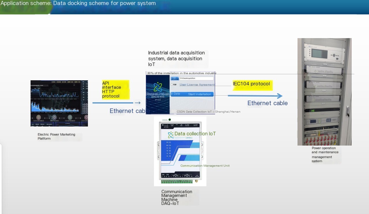
Project situation: The urban investment company currently has a secure electricity and power marketing platform, which operates in an internal network environment and provides an HTTP API interface to obtain data from 531 on-site devices such as smoke detectors, temperature and humidity, and electricity consumption. It needs to be forwarded to the first party's platform through 104 Protocol as a 104 slave station. Use a communication management machine to customize development interfaces.
IEC 104 The protocol (officially known as IEC 60870-5-104)It is widely used in the fields of power systems and industrial automationRemote Communication ProtocolBased on TCP/IP Network implementation of data transmission, mainly used for master station (monitoring center) and slave station (on-site equipment, such as...) RTU、 PLC、 Real-time data exchange between smart meters, etc. Its core is to optimize network transmission performance through the TCP/IP Protocol stack based on the IEC 60870-5-101 protocol (serial version), meeting the monitoring requirements of long-distance, multi device, and high Real-time performance.
1、 Core positioning and characteristics of IEC 104 protocol
Before understanding the master-slave station, it is necessary to clarify the essence of the protocol: IEC 104 is a combination protocol of "application layer+transport layer" - the transport layer is based on TCP (ensuring reliable connections), and the application layer uses the data format of IEC 101 (such as telemetryteleindicationRemote control frame structure), while adding network adaptation function to solve the distance, bandwidth, and multi device access limitations of serial communication.
Its core features include:
- Based on TCP/IP network: Use a fixed port number 2404 As the default communication port, it supports Ethernet, Internet and other IP networks, with no physical limit on transmission distance;
- Reliable transmissionRelying on TCP's "three-way handshake" to establish connections, retransmission mechanisms, and traffic control, to avoid data loss or disorder;
- Real-time Performance optimizationSupport "cyclic transmission" (regular data reporting) and "burst transmission" (event triggered reporting, such as switch displacement), meeting the Real-time requirements for power dispatch and industrial monitoring (usually with a delay of ≤ 1s);
- Multi data type supportCovering the core requirements of remote control systems, including telemetry (analog quantities such as current/voltage), remote signaling (switch quantities such as equipment status), remote control (control instructions such as opening/closing)remote adjustment(Parameter settings, such as constant value modification);
- Standardization and compatibilityGlobal unified standard, different manufacturers' master and slave devices can achieve interoperability through protocols (subject to "consistency testing").
2、 Core definition and functions of Master Station
The main station is for IEC 104 communicationInitiator and Control CenterIt is usually deployed in monitoring rooms or dispatch centers, responsible for "monitoring and control" of substations. Typical equipment includes power dispatch systemsSCADA(Monitoring and Data Acquisition system) server.
1. Core role of the main station
- Connection ManagerProactively initiate TCP connections to the slave station (usually in "passive listening" mode), maintain connection status (such as disconnection and reconnection, timeout detection);
- data requesterProactively requesting data upload from the slave station (such as "summoning telemetry/remote signaling"), or receiving sudden data reported by the slave station;
- Issuing party of control instructionsSend remote control and remote adjustment instructions to the slave station (such as controlling on-site switch actions, modifying equipment parameters), and receive feedback on the execution results of the slave station's instructions;
- Communication monitoring partyMonitor the communication quality with the slave station (such as packet loss rate, delay), record communication anomalies (such as disconnection, frame errors), and trigger alarms (such as sound and light prompts, log recording).
2. Key functional details of the main station
| functional module | Specific function |
|---|---|
| Connection Management | -Configure the IP address, port number, and reconnection interval of the slave station; -Check the TCP connection status. If there is no data after timeout (such as 30s), disconnect and reconnect; -Support the "single master multi slave" architecture (one master connects multiple slaves). |
| Data Acquisition | -Loop collection: Configure the slave station to report full telemetry/remote signaling periodically (e.g. 5 seconds/time); -Summoning collection: actively sending "summoning frames" to obtain specified types of data (such as summoning only fault remote signaling); -Sudden reception: Real-time receives event data triggered by the slave station (such as switch displacement, telemetry limit exceeding). |
| control operation | -Sending remote control commands (such as "opening" and "closing") should follow the "two-step operation" (pre command+execution command) to avoid misoperation; -Send remote adjustment instructions (such as modifying current settings) and receive confirmation frames from the slave station stating that the parameters have been set; -Verify the execution results of instructions (such as checking whether the remote signal has changed position after remote control to ensure successful operation). |
| clock synchronization | Send a 'clock synchronization frame' to the slave station to unify the master and slave station time (accuracy usually requires ≤ 100ms), ensuring consistent event timestamps (such as unified fault occurrence time). |
| Fault handling | -Receive "device fault frames" reported by slave stations (such as slave station Hardware fault); -Detect communication anomalies (such as frame check errors, data timeouts), record logs, and issue alerts; -Support "breakpoint continuation": After reconnection, only the historical data during the disconnection period is obtained (data caching supported by the slave station is required). |
3、 Core definition and functions of Slave Station
The slave station is for IEC 104 communicationRespondent and Data SourceDeploy on site (such as substations, factory workshops), responsible for collecting local equipment data and executing control instructions issued by the main station. Typical equipment includes RTU (Remote Terminal Unit), PLC (Programmable Logic Controller), and intelligent electricity meter.
1. From the core role of the station
- Passive connectorMonitor TCP port 2404, wait for the main station to initiate a connection, and do not initiate a connection actively;
- Data Acquisitionand the reporting partyCollect local Sensor and actuator data (such as current and switch status), and report them according to the requirements of the main station or local event triggers;
- Control instruction executorReceive remote control/remote adjustment instructions from the main station, perform corresponding operations, and provide feedback on the execution results;
- Local status monitoring partyMonitor the status of Hardware itself (such as power supply, communication module), and actively report fault information to the main station when abnormal.
2. Details of key station functions
| functional module | Specific function |
|---|---|
| Connection response | -Monitor fixed port (2404), establish a connection after receiving TCP connection requests from the main station; -If the master station disconnects, the slave station releases resources and continues to listen, waiting for the next connection; -Supports "multiple master and one slave" (requires special configuration, such as different master stations accessing according to priority), but defaults to "single master and multiple slave". |
| Data Acquisition and reporting | -Local collection: periodic collection of telemetry (such as 1s/time), remote signaling (collected when the state changes), and cached data; -Circular reporting: According to the cycle configured by the main station (such as 5 seconds), encapsulate the full telemetry/remote signaling into "data frames" for reporting; -Sudden reporting: When a local event occurs (such as switch displacement, telemetry limit exceeding, equipment failure), immediately package a "sudden frame" and report it to the main station without waiting for a cycle; -Call response: After receiving the "call frame" from the main station, only the specified type of data is reported (such as only reporting the history of remote signaling displacement). |
| Control instruction execution | -Remote control execution: After receiving the "pre command" from the main station, verify the legality of the command (such as whether there is permission and whether the device allows operation), and provide feedback "pre command confirmation"; After receiving the 'execution command', perform the operation (such as opening the circuit) and report the 'execution result' (success/failure); -Remote adjustment execution: After receiving the "remote adjustment instruction" from the main station, modify local parameters (such as fixed values), verify the validity of parameters (such as whether they are within the allowed range), and provide feedback that "parameters have been set"; -If the command is illegal (such as when the remote control device has malfunctioned), report a "command rejection" frame and explain the reason (such as "device locked"). |
| Clock synchronization response | After receiving the "clock synchronization frame" from the main station, calibrate the local system time to ensure that the timestamp is consistent with the main station (if the timestamp of the event is accurate). |
| Local cache and fault handling | -Data caching: Cache historical data from the latest period of time (such as 1 hour), and the main station can "summon historical data" after reconnection to avoid data loss; -Local fault reporting: When the Hardware (such as power supply, communication module) or acquisition equipment (such as Sensor fault) is abnormal, actively report a "fault frame" to the main station; -Frame verification: After receiving the main station frame, verify the frame format, length, and checksum. If there are errors, discard them and do not provide feedback (resend after the main station timeout). |
4、 Communication process between master and slave stations (core interaction logic)
IEC 104 communication between master and slave stations follows“Active control by the master station and passive response by the slave station”The logic and typical process are as follows:
1. Connection establishment stage
- After starting the slave station, listen to TCP port 2404 and enter the "waiting for connection" state;
- The master station configures the IP and port of the slave station and actively initiates TCP connection requests (SYN packets) to the slave station;
- After receiving the request from the slave station, a SYN+ACK message is returned, followed by an ACK message from the master station. The TCP three-way handshake is completed, and the communication connection is established;
- The master station sends a "start character frame" (signal to initiate data transmission) to the slave station, and the slave station returns a "confirmation frame" to enter the "data interaction" state.
2. Data Acquisition stage (taking remote signal displacement as an example)
- Local collection of "switch from closed position to open position" (remote signaling displacement event) from the station;
- Immediately encapsulate the "remote signal displacement burst frame" from the station (including displacement timestamp, switch number, and new status);
- Send burst frames from the slave station to the master station;
- After receiving the frame, the master station verifies its validity, updates the monitoring interface (the switch status turns red), and sends a "confirmation frame" to the slave station (indicating that it has been received);
- If the master station does not receive a confirmation frame (such as network packet loss), the slave station will wait for a timeout (such as 10 seconds) and resend until it receives confirmation from the master station.
3. Remote control operation stage (taking "closing" as an example)
- The operator of the main station clicks the "close" button on the interface, and the main station sends a "remote control pre command frame" (including equipment number and operation type "close") to the slave station;
- After receiving the pre order from the station, verify that: ① the device number exists; ② The current status of the device is "open position" (allowing closing); ③ No local lock;
- After passing the verification of the slave station, it returns a "pre command confirmation frame" and enters the "waiting for execution command" state;
- After receiving the pre order confirmation, the master station sends a "remote control execution command frame" to the slave station (confirming the execution of closing);
- After receiving the execution command from the slave station, drive the actuator (such as a relay) to perform the closing operation;
- Collect the remote signaling status after the closing of the slave station (confirm that it has been closed), and send a "remote control execution result frame" (successful/failed) to the master station;
- The main station receives the result frame, updates the interface status, and records the operation log (such as "2024-05-20 10:00:00, successfully closed").
4. Disconnecting phase
- When the master station needs to stop communication (such as maintenance), it actively sends a "stop character frame" and the slave station returns a "confirmation frame";
- The master station sends a TCP FIN message, the slave station returns a FIN+ACK message, the master station returns an ACK message, the TCP wave is completed four times, and the connection is disconnected;
- If the network is abnormal (such as network disconnection), the main station will detect timeout (such as no data for 30 seconds), actively disconnect, and then retry the connection according to the configured "reconnection interval" (such as 1 minute).
5、 Key Differences between Master and Slave Stations (Table Comparison)
| comparative dimension | Master Station | Slave Station |
|---|---|---|
| role positioning | Control center, data demander, instruction issuer | On site terminal, data source, instruction executor |
| Connection initiation | Initiate TCP connection actively (send request to slave IP: 2404) | Passive listening on TCP port 2404, waiting for the main station to connect |
| Data transmission direction | Mainly receives data from the slave station and issues control instructions | Mainly reporting data to the main station, receiving and executing instructions |
| core logic | Active control (summoning data, issuing commands, monitoring connections) | Passive response (reporting data, executing instructions, feedback results) |
| deployment location | Monitoring room, dispatch center (remote) | Substation, factory workshop (on-site) |
| Equipment form | SCADA server, scheduling terminal, monitoring software (running on PC/server) | RTU、PLC、 Intelligent instruments, measurement and control devices (embeddedHardware) |
| Fault handling | Detect communication abnormalities, proactively reconnect, and record log alerts | Report local fault, cache historical data, wait for the main station to reconnect |
6、 Application scenarios and precautions of the protocol
1. Typical application scenarios
- power systemCommunication between the substation RTU and the SCADA system of the dispatch center, transmitting telemetry (current, voltage, power), remote signaling (switch status), and remote control (opening and closing);
- Industrial AutomationThe factory PLC communicates with the central control room monitoring system to transmit production line temperature, pressure (telemetry), equipment operating status (remote signaling), and start stop control (remote control);
- Municipal EngineeringThe on-site measurement and control terminal of the water/gas pipeline network communicates with the dispatch center to transmit flow rate, pressure (telemetry), valve status (remote communication), and valve control (remote control).
2. Precautions
- Network reliabilityIEC 104 relies on TCP for reliable transmission, but it is necessary to ensure sufficient network bandwidth (to avoid congestion) and low latency (Real-timeperformance requirement ≤ 1s). It is recommended to use dedicated Ethernet in industrial scenarios (to avoid mixing with office networks);
- safety protectionThere is a risk of hacker attacks on TCP/IP networks, and it is necessary to deploy firewalls (restricting port 2404 to only allow access from the main IP) and VPNs (encrypted transmission) to prevent unauthorized devices from accessing;
- Consistency TestMaster and slave stations from different manufacturers need to pass IEC 104 consistency testing (such as checksum format and interaction logic), otherwise compatibility issues such as "able to connect but unable to transmit data" may occur;
- Timeout configurationThe master station needs to configure the "reconnection interval" (such as 1 minute to avoid frequent reconnection occupying the network) and "data timeout time" (such as 30 seconds to avoid misjudging the line) reasonably, and the slave station needs to configure the "retransmission interval" (such as 10 seconds to ensure that data is not lost).


评论
发表评论