Nanzi IEC103 Protocol Power Data Acquisition Technical Solution - Edge Gateway Communication Management Machine Interface Machine 104
As a professional provider of IoT data acquisition solutions and an expert in industrial IoT data acquisition, the editor of Shanghai Data Acquisition IOT Technology Co., Ltd, (daq-iot) hereby presents the following introduction, and sincerely welcomes discussions and exchanges. Supported Communication Interfaces: CAN, RS485, Mbus, 4–20mA, Profibus, CC-Link, HART, digital I/O, etc. Industrial Protocols: Modbus RTU/TCP, HJ212, IEC104, DLT645, DLMS, IEC61850, MQTT, etc. Mail:export@daq-iot.com
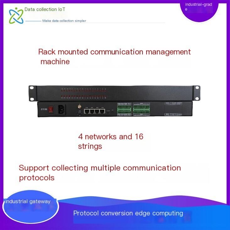
Project background: Multiple electricity meters are supplied by suppliersNGS8801 Communication Management MachineThe main device is connected to the host through the Nan Zi 103 Protocol network port, and the data is called every 5 minutes. The transmitted data does not have a database and is directly displayed on the supplier's client in the window10 system
Requirement function implementation: Process 103 messages and pass the data throughMQTTProtocolTransfer to the third-party platform designated by the customer
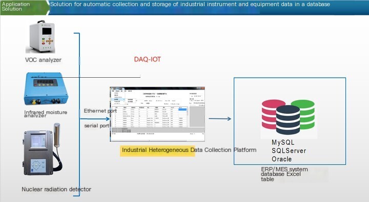
Our company's universal industrial Data Acquisition system supports the collection of IEC103 format data and installationIEC104ProtocolOr MQTT Protocol can report the data.
IEC103 devices support data transmission through transparent transmission: When connecting to the management system, SmartLogger transmits the information of IEC103 devices to the management system through transparent transmission without parsing the data of IEC103 devices
There are two types of message formats in IEC103 Protocol, which are fixed frames and variable frames.
1. Fixed frame
Fixed frame length messages are mainly used to transmit information such as "call, command, confirmation, and response", with only 5 bytes.
Table 1 Fixed frame length message format
1) 10H is the header flag of a fixed frame;
2) 16H is the tail marker of a fixed frame;
3) The link address field is defined as the sub station number, with a value range of 1 to FEH, and its specific value is determined by the user during system design; FEH is used as the broadcasting address for the main station to the sub stations, while 0H is reserved;
4) Verification code=(control domain+link address domain) MOD256;
5) The link control domain occupies 1 byte, but the meanings represented by the uplink and downlink are different.
① The meaning of the link control domain in the downlink (transmission from the main station to the sub station) message is shown in Table 2.
Table 2 Format of downlink message link control domain
② The meaning of the link control domain in the uplink (sub station to main station transmission) message is shown in Table 3.
Table 3 Format of uplink message link control domain
③ RES: Reserved bit (set to 0).
④ PRM: Start flag, PRM=1 when the starting station sends a message, and PRM=0 when the moving station sends a message.
⑤ FCB: Frame Counting Bit, is an important mechanism to ensure information transmission security. The controlled station determines whether to resend the previous frame message by judging whether the FCB has been flipped. The frame count bit FCB of the reset command is usually 0, and the frame count effective bit FCV is 0.
⑥ FCV: Frame Count Significant Bit, FCV=1 indicates FCB is valid, FCV=0 indicates FCB is invalid. The FCV for sending/unanswered services and broadcasting messages is often 0.
⑦ ACD: Request access to primary user data, ACD=1 indicates that the controlled station has primary data.
⑧ DFC: Data Flow Control Position. DFC=1 indicates that the buffer of the controlled station is full and cannot receive subsequent messages.
评论
发表评论