Extended Oil and Gas Extraction Plant OCR Recognition Data Extraction Case
As a professional provider of IoT data acquisition solutions and an expert in industrial IoT data acquisition, the editor of Shanghai Data Acquisition IOT Technology Co., Ltd, (daq-iot) hereby presents the following introduction, and sincerely welcomes discussions and exchanges. Supported Communication Interfaces: CAN, RS485, Mbus, 4–20mA, Profibus, CC-Link, HART, digital I/O, etc. Industrial Protocols: Modbus RTU/TCP, HJ212, IEC104, DLT645, DLMS, IEC61850, MQTT, etc. Mail:export@daq-iot.com
1Background requirements
Project LocationYulin City, Shaanxi Province
Project partyImplementation Unit: Shaanxi Engineering Technology Co., Ltd., End User: Yanchang Gas Production Plant 2 and Plant 3 under Yanchang Petroleum Group
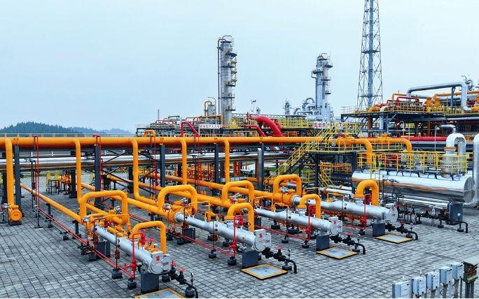
Project RequirementsThe pointer type gauges (pressure gauges, temperature gauges) Data Acquisition are collected on the Yanchang Petroleum Group Safety Production Intelligent Management Platform for unified monitoring and management.
project pain pointsThe distribution of meter points on the gas transmission pipelines of the entire second and third gas production plants is complex and scattered, with different locations. According to the regular production plan, it is necessary to monitor the pressure and temperature data corresponding to the operation pipeline at a fixed time to achieve the purpose of regulation. The traditional approach of manual reading and human-computer interaction for data input cannot achieve the goal of data supervision on the production line. On the other hand, most of the venues are equipped with pointer pressure gauges, temperature gauges, etc., which do not have communication interfaces. Even if some have communication interfaces, the wiring acquisition method for explosion-proof application scenarios is too expensive.
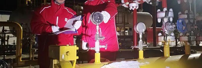
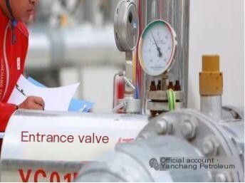
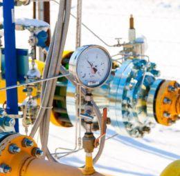
Various pressure and temperature gauges for gas pipelines
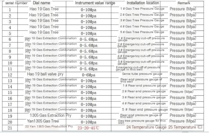
Partial point statistics table
Evaluate implementationAccording to the existing requirements, implement the Data Acquisition of these meters by installing an OCR image recognition and acquisition device(SC-LP-CAM)Powered by batteries and transmitted wirelessly, the instrument data is collected and transmitted to the backend.
IICollect products
The data acquisition product that matches the corresponding meter is our company's image recognition and photography product:Micro power wireless camera meter reader&OCR camera recognition terminal(SC-LP-CAM), Main parameters and functions of the product:
Product Name
Functional Description
Parameter Configuration
advantage
Micro power wireless camera meter reader
The camera meter reading terminal series is a battery powered wireless timed camera meter reading terminal designed for fast meter reading of traditional old mechanical instruments (such as water meters, electricity meters, gas meters, pressure gauges, etc.) or instruments that cannot communicate directly. The camera terminal takes photos at set time intervals and uploads them to the server for analysis and recognition, obtaining instrument readings. Users can view the original images and recognition result data.
The terminal is equipped with a long-life lithium battery that supports data collectionNB-IOT communication methodIt can overcome wireless communication obstruction caused by special on-site environments, greatly simplifying on-site deployment time and reducing construction costs.
1. Characteristics of instrument photo collection
Image format type: jpg
Image Pixel: Supports up to 640 * 480
Collection frequency: 10 minutes to 24 hours, supports remote configuration
Wake up mode: Interval wake-up; Timed wake-up; Alarm clock wake-up
2 Electrical characteristics
Power supply method: 3.6V long-life lithium battery power supply (non rechargeable)
Battery capacity: 8500mAh
Power consumption: current less than 200mA
Standby current: less than 5uA
3 Structural characteristics
Material: PC plastic (shell)
Main protection level: IP65
Water meter size: 135mm × 95mm × 55mm
Meter size: 120mm × 110mm × 50mm
T-shaped size: 82mm × 88mm × 63mm
Main installation method: adhesive or narrow band clamp fastening
4 Work environment
Environmental temperature -25 ° C to 75 ° C, humidity 0 to 95% (non condensing)
1. Powered by lithium batteries, it supports about 3000 photo taking times and can last for about 7 years once a day;2. Built in telecom IoT NB card, with nationwide signal coverage;3. Multiple appearance forms (square, circular, convex), quickly adaptable to on-site industrial instruments;4. Supporting cloud platform, capturing images and regularly pushing recognition results, providing free API interface.5. Clear image quality, recognition accuracy: greater than 99%6. Easy installation, reducing construction troubles and costs.
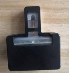
8699150482366458 (QR code automatic recognition)
T-shaped: clamp installation form, suitable for single pointer pressure and temperature gauges
IIIimplementation process
3.1 Technical Proposal
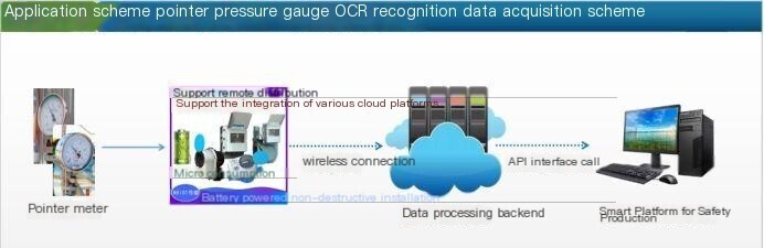
Technical solution topology diagram
The instrument cover is installed with a buckle type recognition terminal, which is recognized through OCR photography and uploaded to the data processing backend. There is no need for wiring on site, simplifying manual implementation costs. Transfer data wirelessly to the cloud platform. The platform provides free API interfaces for docking with third-party platforms, which can be actively called or integrated with our cloud platformMQTT transmissionForm push to the third platform.
863931070091097 (QR code automatic recognition)
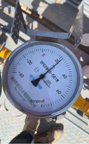
On site installation implementation diagram
Remote docking and debugging
3.2 Factors affecting installation implementation
1) Confirmation provided by the collection meter (suitable for mechanical water, electricity, gas meter collection, or digital display instruments with a constantly lit screen and no jumping on the page).
2) The meter displays the size of the display disk (whether the product can completely cover the display disk), the appearance shape, and whether it conforms to square or circular products.
3) Single line (single pointer) Data Acquisition.
4) Collection frequency (the fastest frequency for battery powered products is once every 10 minutes, which can be set between 10 minutes and 24 hours. If you want to achieve high-frequency collection (once every 5 minutes), considering battery life issues, you need to modify the device to an external power supply version).
5) Power supply method: Conventional battery power supply (with a capacity to support about 3000 photos), can be changed to an external power supply version.
6) Signal (the product usually has a built-in patch antenna, and if the collected meter is in a closed environment, it is necessary to confirm whether the signal is affected. Consider modifying it to an external antenna version).
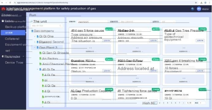
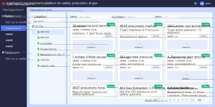
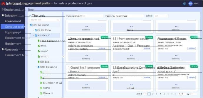
4Display of Implementation Results Data Platform


评论
发表评论