MQTT Protocol Open API Interface -4G Intelligent Remote Control Timer Switch Over/Under Voltage Protector CurrentReal-timeMonitoring Alarm Circuit Breaker Three Phase
As a professional provider of IoT data acquisition solutions and an expert in industrial IoT data acquisition, the editor of Shanghai Data Acquisition IOT Technology Co., Ltd, (daq-iot) hereby presents the following introduction, and sincerely welcomes discussions and exchanges. Supported Communication Interfaces: CAN, RS485, Mbus, 4–20mA, Profibus, CC-Link, HART, digital I/O, etc. Industrial Protocols: Modbus RTU/TCP, HJ212, IEC104, DLT645, DLMS, IEC61850, MQTT, etc. Mail:export@daq-iot.com
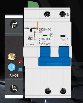
The product supports 4G/WiFi transmission, MQTT or HTTPProtocol. Support customized docking.
DAQ-GP-CB4G 4G intelligent circuit breaker (hereinafter referred to as "circuit breaker"). This product integrates 4G full network communicationMQTTProtocolA new type of electrical equipment that integrates docking, multi-dimensional power protection, and intelligent monitoring functions can achieve intelligent operations such as remote control, electricity metering, and fault alarm. It is widely used in building power distribution, municipal engineering, industrial control, and other scenarios, replacing traditional circuit breakers to achieve intelligent upgrading of power systems.
This manual provides a detailed introduction to the technical parameters, installation specifications, operating methods, MQTT Protocol docking and maintenance of the product. Please read it carefully before installation and use to ensure the safe and stable operation of the equipment.
Product Overview
2.1 Product Features
- 4G full network communication: Built in industrial grade 4G module, supporting mainstream national operator networks, no wiring required, achieving remote flexible control.
- MQTT Protocol docking: Supports standard MQTT Protocol, making it easy to dock with third-party platforms or user built servers to achieve data uplink and instruction downlink.
- Multi dimensional protection function: integrated overload, short circuit, overvoltage, undervoltage, overtemperature, leakage (optional) protection, customizable protection threshold, ensuring electrical safety.
- Intelligent monitoring and measurement: Real-time collects data on current, voltage, power, cumulative electricity consumption, onboard temperature, etc., with high data accuracy and support for data backtracking.
- Multiple control modes: supporting remote MQTT control, local manual operation, and automatic fault tripping, the three modes complement each other, making operation convenient and reliable.
- Strong durability: usingPC flame retardant shellMechanical lifespan ≥ 10000 cycles, electrical lifespan ≥ 6000 cycles, suitable for working environments with a wide temperature range of -25 ℃~70 ℃.
2.2 Technical Parameters
| parameter category | Specifications |
|---|---|
| Product Model | DAQ-GP-CB4G |
| Extreme specification | 2P (live wire+neutral wire)/4P (three-phase live wire+neutral wire) optional |
| Rated Voltage | 220V/400V AC 50Hz |
| rated current | Maximum 63A, measurement range 0~600A, accuracy 0.01A |
| breaking capacity | Ics: 6000A (residential scenario)/10kA (industrial scenario optional) |
| contact method | 4G full network, supports MQTTProtocol, optional RS485 backup communication |
| standby power | ≤3W |
| working environment | Temperature: -25 ℃~70 ℃ (extreme), -5 ℃~35 ℃ (conventional); Humidity ≤ 95% RH (no condensation) |
| Installation Method | Installation of 35mm standard guide rail |
| Product dimensions | 2P:54×100×77mm;4P:107×100×77mm |
| protection function | Overload, short circuit, overvoltage, undervoltage, overheating, leakage (optional), threshold adjustable |
3、 Installation and wiring
3.1 Installation Preparation
1. Confirm that the installation environment meets the product requirements, is away from flammable, explosive, humid, and strong electromagnetic interference sources, and reserves sufficient heat dissipation space.
2. Check whether the appearance of the equipment is intact, the shell is not damaged, the wiring terminals are not deformed, and the accompanying accessories (fixing buckles, wiring terminals, instructions) are complete.
3. Prepare the necessary tools: screwdriver, wire stripper, voltage tester, grounding wire, shielded twisted pair cable (if communication needs to be expanded), etc.
3.2 Installation steps
- Align the circuit breaker buckle with the 35mm guide rail, press firmly to clamp the equipment onto the guide rail, ensuring a secure installation without looseness.
- Adjust the installation position, with the commonly used operating surface facing in an easily accessible direction, and the distance between equipment and the inner wall of the distribution box should not be less than 10mm.
- After confirming that the superior power supply is disconnected, perform wiring operations. After wiring is completed, check the correctness of the wiring again to avoid reverse or missing connections.
3.3 Wiring Instructions
1. Strong current wiring: The upper end is the power input terminal (live wire L/three-phase L1, L2, L3, neutral wire N), and the lower end is the load output terminal. Corresponding wiring is sufficient, and the input and output are zero. The wiring terminal should be selected with an appropriate wire diameter to ensure a secure connection and avoid overheating and false connections.
2. Grounding wiring: The equipment grounding terminal (marked as "PE") should be reliably connected to the grounding wire of the distribution box grounding strip, and the grounding resistance should be strictly controlled within 4 Ω.
3. Communication wiring (optional): If expansion is requiredRS485 communicationConnect the shielded twisted pair cable to the RS485 interface (A and B ends) of the device, and ground the shielding layer at one end to avoid interference.
Note: After the wiring is completed, it is necessary to check the correctness of the wiring again before powering on to ensure that the live wire, neutral wire, and ground wire are not connected incorrectly, and the load current does not exceed the rated current of the equipment


评论
发表评论